


Another 10 Circuit Components You Should Know
It's that time again to review all the oddball goodies available in electronic components. These are things you should have in your bag of tricks when you need to design a circuit board. If you read my previous posts and were looking forward to more, this article's for you!
1. Bus switches
I can't believe I haven't mentioned bus switches before. What is a bus switch?
There are lots of different options for switches:
- mechanical switch / relay: All purpose, two contacts are hooked up together. Advantages: switch nodes are floating and can be hooked up anywhere in a circuit, essentially zero leakage current. Disadvantages: mechanical wear, bounce on connect/disconnect
- discrete MOSFET. Good for power switching. Advantages: easy to control, fast switching (hundreds of kilohertz), can pull a circuit node down (N-channel) or up (P-channel), available all the way up to hundreds of amps, a few hundred volts, behavior is resistive (low voltage drop at low currents). Disadvantages: may have moderate leakage current especially at elevated temperatures, gate drive circuits are relative to MOSFET source, not readily available for small-signal applications, not bidirectional in the off-state.
- discrete IGBT. Good for power switching at high voltage, beats MOSFET in efficiency above 100-200V. Advantages: Workhorses of modern power conversion. Disadvantages: same disadvantages as MOSFET, plus more expensive than MOSFET, higher voltage drop (Vce) even at low currents, doesn't switch as fast, has longer time to completely turn off, not appropriate at all for small-signal applications.
- discrete bipolar transistor. Good for small-signal switching with low leakage currents. Advantages: works well in low-voltage circuits (sub-1V), extremely low leakage (nA), really cheap (in large quantities, 1-2 cents). Disadvantages: Drive circuit relative to transistor emitter, requires current to maintain on-state, kind of a pain to turn on/off fast, has nonzero voltage drop (Vce) even at low currents.
- AC switches: triacs, SCRs, and other thyristors. Advantages: turn them on, and they stay on for the rest of the AC cycle, available at very high power. Disadvantages: turn them on, and they stay on for the rest of the AC cycle; drive circuit is a pain.
- solid state relays: triacs/SCRs prepackaged, often driven with isolated inputs. Advantages: Easy to use with AC mains circuits. Disadvantages: relatively expensive, turnon/turnoff restrictions can be tricky.
- analog switches: precision MOSFETs + integrated gate drive circuitry, meant for low-current precision applications. Advantages: available at moderate cost, easy to use, variety of specifications (switch speed, on-resistance, voltage range, inter-channel coupling, turnon/off crosscoupling, etc.) Disadvantages: need external power supply, some analog switches (HC4066, HC405x) have moderate leakage current (1uA) and may not be appropriate for high-impedance applications — read the fine print.
- digital multiplexers/buffers. Advantages: meant to work at really high speeds (tens or hundreds of megahertz), adds buffering. Disadvantages: need external power supply, doesn't actually connect input to output so you have to know which side is an input and which side is an output.
Which brings us to a bus switch. Here's the circuit diagram of a Fairchild NC7SZ384 bus switch:
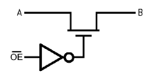
It's basically just a small-signal N-channel MOSFET with integrated drive circuitry, meant to be fast, with switching times in the low nanoseconds, relatively low on-resistance (1-10 ohms) and low capacitance. The low on-resistance applies for input/output signals that are more than a volt or two below the bus switch power supply. As you get closer to the positive power supply, the resistance increases rapidly. They also generally have a defined "off" behavior if they are left unpowered.
When you need to interface digital signals directly (no buffering), bus switches are a good choice. They come in a variety of flavors, from single to multibit, and plain on-off to a multiplexer topology, and they can be fairly inexpensive (sub 10-cents for the NC7ZS384 in moderate quantities).
Bus switches are one of the few options for switching and multiplexing I2C signals because of their bidirectional character. Every once in a while a question comes up on an EE forum about I2C multiplexing, and one suggestion is to use discrete MOSFETs with the gate controlling the "on" state. Yeah, you can use a discrete MOSFET; it's almost like a bus switch and can be slightly cheaper, but the parasitic capacitances of a discrete MOSFET (even a small one) can be problematic. Oh, and it only blocks voltage in the "off" state in one direction (parasitic diode in the other direction). So my advice is use a bus switch.
2. Thermocouple signal conditioning ICs
Some applications just need the accuracy and temperature range of thermocouples. They can be a real pain to use, though. You need to accomodate four things with thermocouple signal conditioning:
- Noise filtering — thermocouples are typically two long wires yielding a microvolt signal, aka an antenna. You must filter out high frequency noise before it gets to any semiconductor components, otherwise you'll get unwanted low-frequency signals that comes from the nonlinear response of semiconductors.
- High gain / resolution — a thermocouple temperature coefficient is in microvolts per degree C (μV/°C).
- Nonlinear processing — the temperature coefficient changes with temperature.
- Dependence on the temperature of metal junctions — net thermocouple voltage depends on the temperature at dissimilar metal junctions. You have one junction where you want to measure temperature, and at least one more (usually two) where the thermocouple wires connect to signal conditioning circuitry (this is called the "cold junction"), and possibly others if you're not careful about connectors. Most thermocouple signal conditioning includes some careful mechanical design at the cold junction, to prevent this area from having thermal gradients and fluctuations (e.g. air currents or sunlight) through insulation and providing thermal mass. This is called the isothermal block. There is usually a thermistor or other temperature sensor here to provide cold junction compensation.
(Fortunately there's a lot of good literature on how to deal with these issues. See for example Bob Perrin's article in Circuit Cellar.)
For years, the Analog Devices AD594 and AD595 were the primary choice for a 1-chip solution that handled thermocouple signal conditioning. They are only available in DIP ICs, however, and are not cheap — at the time of this writing, Digikey lists the AD594AQ and AD595AQ at \( 9.34 in 1000 piece quantity.
Recently there's been a little more competition in the thermocouple signal conditioning market:
- Analog Devices AD8494/AD8495/AD8496/AD8497 is a revamp of the AD594/AD595 in an MSOP package, with budgetary pricing under \)2 in quantity.
- Maxim MAX81350/81351 thermocouple-to-1-wire converters. Oh, how I hate thee, Maxim; thou advertisest with lofty promises, and thy prices are a rich man's realm, and thy products have lead times stretching to the end of days. But when you need something with a thermocouple in, and digital out, well... I guess you're stuck with them.
The problem with thermocouples is they are social creatures: you rarely find systems with only 1 thermocouple. Usually there are several, because physicists are involved, and... well... they like measuring everything. So in a practical system I would probably use an analog multiplexer to cover the necessary number of channels, an instrumentation amplifier, a thermistor, and a microcontroller and handle the signal processing myself in software.
For these next few items, we'll veer away from silicon and over to plastic and metal.
3. Plain old metal for circuit boards
While looking for zero-ohm resistors (which I mentioned last time), I ran across Harwin's EZ-BoardWare. These are small metal pieces useful for connections, grounding, and holding coin cells.
They reminded me of similar parts from Keystone Electronics, which is one of the major manufacturers of plain vanilla stuff like test points and PCB terminals. They've got a pretty nice and inexpensive high-current (30A) screw terminal:

4. PCB Stiffeners, and a sad story
I have always wanted to use a PCB stiffener / bus bar. If you've had to do any high-current PCB design, you'll know what I mean: carrying more than about 10A of current on a circuit board starts to make things difficult. If you want to stay with 1 oz. copper (=35 μm), traces need to be wider; if you want to keep trace widths manageable (e.g. under 1cm wide), then you need to start considering heavier copper plating, in which case there are implications to PCB feature size — trace width and spacing can't be as small as with 1oz copper boards. If you have constraints in trace width and copper thickness, then there aren't too many options; you can use multiple board layers in parallel with via stitching between them. Connectors get harder to find. You have to worry about thermal relief on component pads to ensure that soldering/desoldering is tractable. IR drops along traces can't easily be neglected, and the board can heat up. Like I said, a headache.
Having said that, it's still possible to carry 100A on a circuit board without having to use exotic materials or components, you just have to be really careful about all these things. High-power systems more commonly use bus bars which keep the high-current paths off the circuit board; industrial transistors and capacitors have screw-on connections to be able to attach directly to a bus bar without having to deal with circuit boards.
Anyway, I once saw this ad for PCB stiffeners from CCI (Circuit Components Inc) where they used stamped plated metal parts to carry current and help prevent the PCB from bending and damaging SMT components.
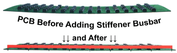
(illustration from E-FAB Inc.)
What a brilliant idea! The specs on the CCI stiffeners ("Rigid/Bus© Bars") were in the 35 - 70 microohms per inch range; the copper plating was around 1mm thick, equivalent to a 29 oz. copper circuit board (!!!). You could buy two-layer parts for carrying return currents; this minimizes stray leakage inductance and magnetic fields. And it's vertical -- so if you're like me and rarely have to design low-profile PCBs, you can actually make use of vertical space above the circuit board and have a small on-board width.
So I knew this was a component to put on this list, even if I'd had an occasion to use it myself.
When I went to find the manufacturer's website, however, I ran out of luck. The internet domain they used is for sale, and I finally found a notice that in July 2012 all their stock was auctioned off.
There are other companies making PCB stiffeners: E-FAB, Purcell, Storm Copper Components, Electronic Systems Packaging, and a few others, but none of them have a good set of electrical specifications (wah wah wah!). And of course there are plenty of companies who will be glad to sell you custom stamped bus bars; I'm just not aware of any off-the-shelf stock products like the CCI PCB stiffeners.
Alas...
The idea's still a good one, though, and maybe someone will step up to the plate and sell some of these with good electrical specs.
5. Stromversorgungselemente
I love that it's so easy to spell and parse long German words. Strom = power, versorgungs = supply, elemente = elements.
Würth Elektronik sells some interesting Stromversorgungselemente:

These are multi-pin press-fit PCB terminals. And the larger terminals from Würth are rated at over 100A!
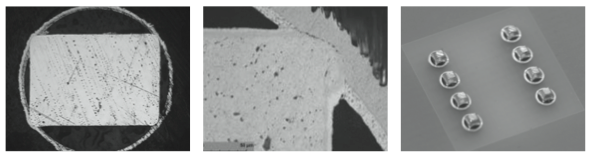
Each pin provides 4 areas of gas-tight, reliable contact with a plated PCB hole of the correct size. It may look inefficient compared to soldering (look at all that "dead air space"!) since only about 3% of the hole circumference makes electrical contact, but the fine print with soldering is that tin- and lead-based solders have electrical conductivities that are 7-10 times lower than copper, and Würth claims they get a much more reliable connection with press-fit electrical connections.
We used these parts a few years ago on a design that needed to carry 100A continuous current, 200A peak, and they worked very well.
6. Terminal blocks with pushbuttons
There's a dirty little secret about connectors. The number of connect/disconnect cycles can be rather limited. With a few rare exceptions (consumer cables that get plugged/unplugged frequently, like USB or HDMI cables), don't expect more than 100; some may only guarantee good contact for 5 or 10 cycles. Some examples:
- Molex KK series: 25 cycles.
- Molex Micro-Fit series: 30 cycles.
- Hirose DF50 series: 30 cycles.
- TE/AMP Mate-N-Lok series: 50 cycles.
- TE Blade and receptacle connectors: 10 cycles.
In industrial settings with frequent assembly/disassembly, this kind of contact cycle life may only last a few weeks. So for a lot of these types of applications you will frequently see screw terminal blocks. Lots of companies make them: Phoenix Contact, WAGO, Weidmüller, Molex, TE, Wieland, Würth, etc. etc.

You've seen these before. They're usually green — although they come in lots of colors — you loosen the screw on top, slide in a wire with the insulation stripped off the end, tighten the screw, and hope you've made good mechanical and electrical contact so the wire won't pull out.
It takes a long time to screw and unscrew these, it's hard to guarantee you've inserted the wire correctly, and strands of the wire usually end up squished and sometimes torn off. It doesn't take long to get sick of them.
Most of these manufacturers also make spring terminals, where the wires are held in by a strong spring contact, rather than a screw contact. These can actually be more reliable than the screw terminal, because the wires are held in with more precisely controlled compression forces. You either put a screwdriver in a slot to open up the spring slot, or you pull a lever, or push a button.
For small wires, I like the 2.5mm style with pushbuttons:

The buttons are pretty easy to engage, so they're a lot quicker to use than the screw terminals.
Okay, back to silicon:
7. Opto-FET
Galvanic isolation is one of those things that you just can't do without in certain applications. Usually it's for safety reasons, if part of the circuit is operating relative to earth ground, and part of the circuit is operating relative to the AC mains voltage. And if you need to work with digital signals, there's a lot of parts out there which will work for you.
Sometimes you need to work with analog signals across an isolation barrier, however. And maybe this side of the isolation doesn't have an accessible power supply. For example, you have a data acquisition system with analog inputs, and for some stupid reason the DAS designer only brought the inputs and analog ground out to a connector, with no source of 3V or 5V available.
What can you do? Well, the old-school solution was to use relays. But they're relatively large and expensive and power-hungry, and they take milliseconds to turn on or off, and they make clicking sounds. (Before you laugh, try working on a system with lots of mechanical relays.)
And you have to be careful about buying relays for use with small voltages and currents — sometimes the contacts won't last long if the currents are small. They'll oxidize, and the only way to guarantee the oxidation won't build up is to use a high enough load current to punch through the oxidation layer during relay switching.
I like FET-output optoisolators. They present an electrical load that is very well-matched to analog circuitry, switching from high-impedance to low resistance when the input is activated. They're not quite as inexpensive or fast as regular digital optoisolators, but they do offer an attractive alternative to relays for analog circuits. You can even use them as variable resistors (although the input-current to output-resistance transfer function is nonlinear and unpredictable).
- Toshiba TLP222A: 60V 2 ohm max Rdson, 2msec on-time, 0.5msec off-time.
- Fairchild H11F1M: 30V 200 ohm max Rdson, 45 μsec on- and off-time.
- IXYS CP Clare CPC1017N: 60V 16 ohm max Rdson, 10msec on- and off-time.
If these voltages or Rdsons don't work for you, you can also use your own MOSFET with a photovoltaic optocoupler like the Vishay VOM1271:
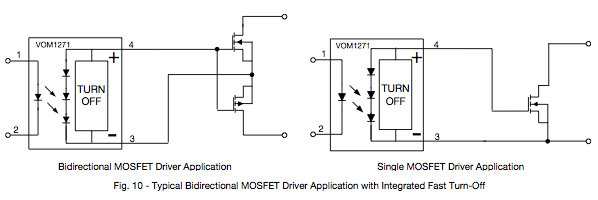
The optocoupler generates a voltage around 8V, and can drive a very low current load: they're spec'd at 6 microamperes minimum short circuit current output, for 10mA input current. Perfect for MOSFETs if you don't need them to turn on or off quickly — switching times with 200pF loads are characterized at 53μsec typical on-time, 24μsec typical off-time. Use the dual-MOSFET configuration if you need bidirectional voltage blocking capability, or the single-MOSFET configuration if you only deal with unidirectional voltage blocking. Be advised that this is a very weak driver, not advised for PWM circuit operation. I've got a story to share another day on that topic. I do like the VOM1271's "integrated rapid turn-off circuitry", but they don't give any specifications for what it's supposed to do. No spec, wah wah wah. (There's a theme here....)
Finally, now that I work for Microchip, I have to say something about a few of our parts that I really like. (Disclaimer: these are my own opinions and I am not speaking on behalf of my employer.)
8. Autozero opamps
Microchip acquired TelCom Semiconductor back in 2001 and got into the analog IC market. One of the TelCom parts I liked was the TC913 chopper-stabilized op-amp.

The idea's pretty sweet: you use an auxiliary opamp to drive the Vos on the main op-amp to zero by altering an internal adjustment terminal on the main opamp. But then that requires the auxiliary opamp to have very good offset voltage... so you can do this by having it split its time by adjusting itself half the time, and adjusting the main op-amp the other half of the time.
Guess when chopper-stabilized op-amps were invented: Edwin Goldberg came up with the idea back in 1949! Unbelievable, isn't it? This was back in the days when op-amps were expensive vacuum tube beasts.
In any case, TC913s were fairly reasonably priced and could bring the offset voltage down into the microvolt range. You can still buy a TC913, but they're expensive (Microchip rarely discontinues parts as long as there's some demand, although the price may increase to cover the opportunity/maintenance cost)... but we have a number of inexpensive autozeroing opamps like the MCP6V31 or the MCP6V26.
Use these when you need to amplify very small signals (like strain gauges), either with high gain, or as a preamp stage. What do I mean by preamp stage? Well, having a single op-amp handle a 1000x gain circuit isn't really a good idea. It really cuts down the bandwidth: a reasonably fast 10MHz GBW opamp turns into a 1000x gain 10kHz bandwidth circuit. If you want to keep the bandwidth up, use a 2-stage approach: two 10MHz GBW opamps, each with a gain of 32, gives a net gain of 1024 with a bandwidth of about 300kHz. The first amplifier stage is the one where the offset is most critical. I'd probably combine an MCP6V26 (GBW = 2MHz) as the first stage with something else as the second stage.
Better yet, use the auto-zero opamp as an auxiliary opamp, to adjust a bias input for a high-bandwidth opamp. Here you could get away with using the lower-bandwidth MCP6V31 (300kHz GBW) for offset adjustment, with a high-bandwidth opamp of your choice. (This tends to work better in inverting gain configurations, where the opamp input terminals stay at constant voltages.)
Yeah, there are other companies that make auto-zero opamps, but Microchip's opamps tend to be more cost-competitive.
9. CTMU (Charge Time Measurement Unit)
The touch-screen and touch-sensing business has exploded in the last ten years. Microchip came up with something called the Charge Time Measurement Unit, or CTMU, to address capacitive touch-sensing. It's a peripheral on many of the PIC microcontrollers (here's one of the reference manuals for the CTMU). The CTMU module amounts to a couple of things that work together:
- a stable current source, usually one that can be configured to multiple ranges (reasonably accurate, but stability is more important)
- a stable capacitor (the one used in the ADC)
- features that allow cooperative operation with on-chip comparator/ADC/timer/voltage reference
The idea is that you can do accurate ratiometric measurements between unknown capacitors and a reference capacitor, by comparing charge times of the reference capacitor and the unknown capacitor using the same current source, comparator, and reference voltage.
Pretty simple and pretty powerful.
10. PPS (Peripheral Pin Select)
My favorite feature of our microcontrollers is a pretty mundane one. You must have faced this issue before: you're picking a microcontroller, so you need to make sure that it has all the features you want — UART, ADC, PWM, SPI, I2C, timer, comparator, etc. etc. And it's not enough to check off the feature set; you have to look closely at the pins and make sure that the on-chip resources you need don't conflict. There's nothing worse than picking a microcontroller and finding out that the UART and SPI functions you want to use are only available on the same pin.
Or let's say you're using one microcontroller for a few years, and you want to use a new one that's better and has the same pin count. It's unlikely to have the same pinout though, so you'll probably have to respin your circuit board...
Microchip's solution to these problems are something called Peripheral Pin Select. Basically it's a giant multiplexer. You want to use a UART? Fine! Which pin do you want to use it on? It's your choice! You just set a couple of registers, and the UART RX and TX lines get hooked up to the pins that you select.
This works for a lot of the Microchip peripherals with digital functions. The types of peripherals that don't use PPS involve more delicate I/O functions that aren't as easily multiplexed:
- the analog functions (ADC, onboard opamps and comparators)
- in-circuit debugging ports and JTAG (very specialized)
- I2C (because of its bidirectional character)
- PWM (fast outputs, and because system reliability wants these to be on fixed pins)
- PWM fault input (system reliability)
- oscillator I/O pins (very specialized, system reliability)
- reset pin (very specialized, system reliability)
This is a big deal when you're designing systems with low pin count and even moderate pin count devices. It's not a high-profile feature, but it's my favorite.
Okay! That's it for today; I hope you enjoyed the article. Good luck with your next circuit design!
© 2013 Jason M. Sachs, all rights reserved.


- Comments
- Write a Comment Select to add a comment
My favorite board stiffener can be found here: http://www.compufab.com/Screw.aspx
You cut it to any desired length and you use machine screws (6-32 or 4-40, depending on stiffener model) anywhere and in any desired quantity. The inside of the stiffener has a special set of grooves its full length that act as a threaded hole so you don't need to use self-tapping screws.
They say that it can be used to handle current, but I haven't used one for that purpose yet.
Best regards,
Don Lucas
To post reply to a comment, click on the 'reply' button attached to each comment. To post a new comment (not a reply to a comment) check out the 'Write a Comment' tab at the top of the comments.
Please login (on the right) if you already have an account on this platform.
Otherwise, please use this form to register (free) an join one of the largest online community for Electrical/Embedded/DSP/FPGA/ML engineers:


