


Byte and Switch (Part 1)
Imagine for a minute you have an electromagnet, and a microcontroller, and you want to use the microcontroller to turn the electromagnet on and off. Sounds pretty typical, right?
We ask this question on our interviews of entry-level electrical engineers: what do you put between the microcontroller and the electromagnet?
We used to think this kind of question was too easy, but there are a surprising number of subtleties here (and maybe a surprising number of job candidates that were missing them), so read on.
Here's a sketch and some more details to get you thinking.
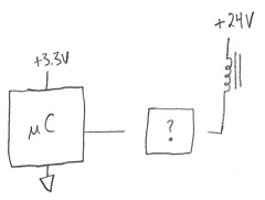
The microcontroller is powered off of 3.3V. The electromagnet is designed to run off a 24V supply, and we'll connect one side of it to the positive terminal 24V supply and the other side... well, we'd like to connect it to the negative terminal of the 24V supply when we want the electromagnet on, and disconnect it when we want the electromagnet off.
The usual answer is to use either a relay or an N-channel MOSFET, hooked directly as shown below for a MOSFET (Q1). A relay in this situation usually isn't practical, because a MOSFET is faster and cheaper, and the relay requires more current to energize the coil than a microcontroller can deliver. So we use a MOSFET. Great... except there are some problems.
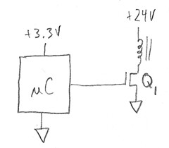
Let's pick a MOSFET: let's say the electromagnet draws 200mA or so at 24V, for a power consumption of 4.8W. In order to have plenty of design margin, we pick a 40V MOSFET rated for 1A with proper heat sinking. Let's hook it up, and use the microcontroller to turn on Q1. Then we get voltage across the electromagnet coil, which looks kind of like an inductor with some series resistance. Because of the inductance, it takes a little while for the current to build up, usually in the 5-50 milliseconds range, until it reaches the steady-state current of 200mA.
Now we decide to turn off Q1... BANG! There's a pop, along with that pungent smell of burnt silicon and a wisp of smoke from the poor little MOSFET. Alas, we've let the magic smoke out, because there was still energy stored in the electromagnet's inductance, and it didn't have anywhere to go except through Q1. But the switch was turned off, you say! Well, sure, but remember, we bought a 40V part, and the inductance is going to generate as much electromotive force as necessary to keep the 200mA of current flowing until its stored magnetic energy dissipates, and 40V is nothing. If you measured the voltage between the MOSFET's source and drain with an oscilloscope, you'd probably see 50-60V for a few milliseconds during this "event": the breakdown voltage of the transistor has been reached, at which point it conducts whether you like it or not.
The fix for this is to add a freewheeling diode D1, as shown below. When Q1 turns off, the current flowing through the electromagnet flows around in a circle through D1, and with a diode drop across the coil, the current decays slowly.
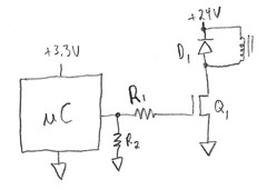
There are also two resistors that should be in the circuit as well. R1 is a series resistor, usually in the 100-1Kohm range, between the microcontroller and the transistor, which serves a few purposes. The main one is to limit the current into the MOSFET gate during turn-on. MOSFETs don't need any gate current in steady-state, but they have parasitic capacitances between the gate and the other two terminals, and to turn that switch on, you need to charge them up. Most MOSFET manufacturers specify gate capacitance (Cgs and Cgd for gate-source and gate-drain) and gate charge (Qgs and Qgd for gate-source and gate-drain charge) -- we don't buy from manufacturers that don't specify these parameters. In any case, if you hook the MOSFET gate directly to the microcontroller output, the current that flows during the turn-on and turn-off transients can exceed the rating of the microcontroller. So you want to limit this current to a reasonable value, put a resistor there. It affects the turn-on and turn-off speed of the transistor, so it shouldn't be any larger than necessary.
The other reasons for adding R1 have to do with fault propagation and high-frequency oscillation. If Q1 fails, sometimes the gate and drain may be shorted together. Having R1 in the circuit can prevent damage to the microcontroller. The MOSFET also has parasitic inductance in its source lead, and this can cause some nasty switching transients; having at least 10-20 ohms will dampen any potential oscillation.
The resistor R2 is there so that when the microcontroller is powering up, or is held in reset, and its internal output is high-impedance, the MOSFET Q1 has a gate that is held at a defined voltage. If you don't hook up R2, Q1's gate is floating when the microcontroller is in reset. If you add R2, you ensure the gate is pulled low and the transistor Q1 is off.
Whew! That's a lot of thought for a simple switch.
To put it another way, think about the ways in which we've discussed that a MOSFET is not an ideal voltage-controlled switch:
- limited drain-source breakdown voltage
- parasitic capacitance
- parasitic inductance
Part 2 of this blog will cover some other limitations of MOSFETs and explain why there are better alternatives in some other "simple" switch applications.


- Comments
- Write a Comment Select to add a comment


R1 protects from parasitic capacitances in the mosfet that can generate currents which may find their way into your mcu and damage it?
R2 mainly controls that floating voltages dont accidentally activate the gate.
Ok how would I go about calculating the resistor values for this? Say Im using a 12V source for a solenoid and an IRLB8721 n-mosfet. I believe I need the mosfet datasheet to somehow calculate the currents generated by it? What parameters do I need to look at?

let me try formulating simple way like tihs:
a) R1
IRLB8271 is a 30V 62A Mosfet. Leakage current Igss = 100nA (@Vgs = 20V) -> so minimum virtual resistor between Gate and Source is 200MegaOhms. I suggest value of R1 = 2MegaOhms to obtain 99% input voltage reaching the Gate.
b) R2
Make this simple to be same with R1 = 2 MegaOhms.
c) Solenoid Commutation Speed
Ciss = 1077pf -> RC time = R1 X Ciss = 2Meg x 1nF = 2 miliseconds. --> to be safe, multiply this with number 5 to make it one stroke duration time -> 2ms x 5 = 10msecond. -> inverse this to be Solenoid Commutation Speed, we get result as 100 times per second of maximum number of solenoid commutation speed.
d) maximum solenoid current
At 100Celcius, this MOSFET capable for delivering 44 Amp load current. To be save, choose only solenoids with working current not more than half of this, say 22 Amperes. Do not more.
That is it!
I hope my simple calcutation will works.
Good Luck.
There are a few important thing missing is this tutorial.
1: "The microcontroller is powered off of 3.3V": it means that you only have 3.3V (Or better yet: +/- X%) to drive the MOSFET into saturation.
MOSFET's rated at 40V which can be driven from 3.3V - 2% can be very hard to find. It might be more practical to use a transistor if the current is small.
2: switching speed:
R1 will protect the microcontroller from damage. But it's more important to size R1 for the required switching speed. Don't make things faster then they need to be.
3: the miller capacitance be be increased in order to control the turn on behaviour.
Pull up and pull down resistors cure a lot of floating line problems.
To post reply to a comment, click on the 'reply' button attached to each comment. To post a new comment (not a reply to a comment) check out the 'Write a Comment' tab at the top of the comments.
Please login (on the right) if you already have an account on this platform.
Otherwise, please use this form to register (free) an join one of the largest online community for Electrical/Embedded/DSP/FPGA/ML engineers:


