


Endianness and Serial Communication
Endianness is a consideration that is easily overlooked in the design of embedded systems. I myself am amply guilty of this oversight. It’s something you don’t ever have to worry about if you’re only working with a single processor or two processors that have the same endianness. You can even avoid it if you have two processors that have different endianness but never transmit data between themselves that consists of more than one byte. It’s easy to lull yourself into a false sense of security that you’ll never have to worry about endianness - until it costs you a whole day of debugging because you’ve been reading a memory map backwards.
It’s not a waste of time to learn about endianness before it causes you stress. It’s not even that difficult. In this article I’ll demonstrate how to account for different endianness between two systems trying to communicate over a byte-oriented serial link.
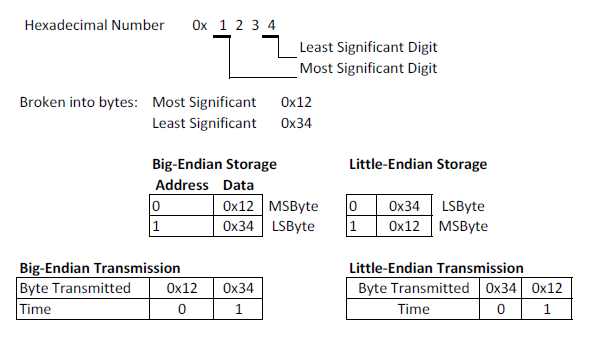
First, let’s get some background. As always, you should read the Wikipedia article on endianness for the full details. Briefly, endianness determines what order multi-byte data is stored in memory and transmitted across serial links. For example, if you have a 16-bit variable it’s made up of two bytes: a high byte and a low byte. Bits 0-7 are stored in the low byte and 8-15 are stored in the high byte. Many processors allow individual bytes to be addressed in memory - so the fundamental question is where is the high byte stored in relation to the low byte? For serial links only one byte can be transmitted at a time, so which is transmitted first - the high byte or the low byte?
There are two answers to this question: big-endian and little endian. Below is a graphic explanation of big-endian vs. little-endian storage and transmission.
Endianness comes into play when data stored in memory needs to be interpreted by an outside source or transmitted to an outside system. Recently I’ve had to deal with endianness when I was transmitting 16-bit accelerometer data to my desktop so that I could process it with Octave. To illustrate the process and help avoid pitfalls I’ve created an example program that transmits 16-bit data from an ATMega328P as well as Octave scripts to plot the received data. It's worth noting that while this code focuses on handling endianness, it's also a demonstration of how to get data out of your microcontroller and plot it on your PC.
The source for the microcontroller program is here. Timer 1 is configured for a 1ms period. Every time the timer interrupts, the accelerometer data is sampled using the full 10 bits of the A/D converter. A 16-bit variable holds the result of the conversion. The UART is configured for 8 data bits, 1 stop bit, no parity and 38400bps. The code has a nifty feature wherein the transmission of data can be enabled or disabled by transmitting an ASCII ‘0’ character (0x30) to the microcontroller. The endianness issue comes into play because the AVR doesn’t have a way to transmit 16-bits of data through the UART in a single transaction: the 16-bit value has to be transmitted in two single-byte transactions. The endianness of the system receiving the bytes determines what order the high and low byte of the 16-bit value need to be sent. For reference, the ATMega328P stores data in memory in little-endian order. Keep in mind that this doesn’t determine the endianness that the transmitted UART data has. The ATMega328P can transmit data in either order and in this code allows the endianness of the transmission to be selected in the code via a preprocessor definition.
The system receiving the data in this case is a generic x86 desktop PC. The endianness of x86 processors is little-endian (which is the same as the ATMega - not that this saves you from having to account for it when you transmit serial data). The application I’m using to plot and analyze the accelerometer data is Octave. Octave is an open-source Matlab substitute. It has all of the basic functionality of Matlab but fewer toolbox add-ons. Despite its lack of some advanced features it’s more than enough to develop simple plots, generate filters and do basic numerical analysis. The end goal of this process is to use Octave to plot the accelerometer data from the microcontroller. I use the Octave 3.6.4 MinGW port for Windows. Directions for download of the base and additional toolboxes can be found here.
While Octave is capable of this it doesn’t have the ability to access the serial port. As a result, the data has to be saved to a file which Octave can then read and plot. To handle reading the serial port and saving the file I use a program called Realterm. Realterm is a full-featured serial terminal program - that is to say, it lets you view data from serial ports in a variety of ways. It has a lot more features than I’ve ever used but it’s simple to use to capture data from a microcontroller in a binary file that Octave can read. You can download Realterm from here. Note well: if you are using Windows 7 you have to install and run Realterm as an Administrator.
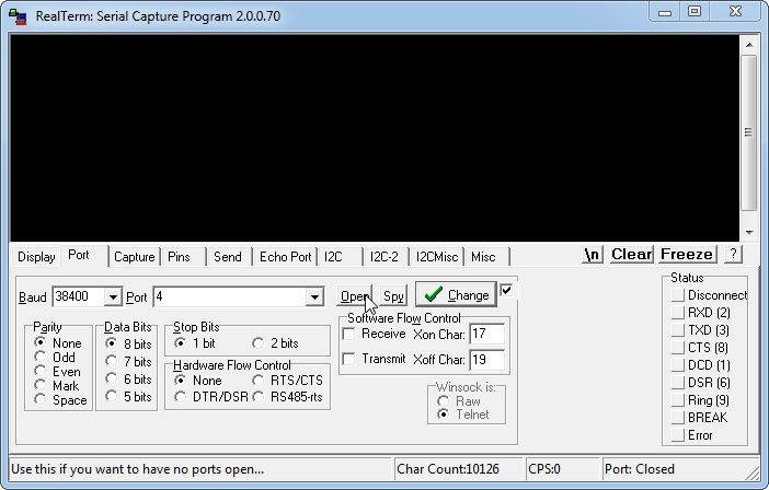
Once you have it installed you can run it (again, run as Administrator under Windows 7) and configure it to access the serial port your microcontroller will be communicating on. You should configure all of these settings before applying power to the microcontroller. The first tab to configure is the Port tab. All of the settings here have to be the same as they are in the microcontroller for this to work. Below is a screenshot of my settings:
Serial port settings:
-
Baud Rate: 38400
-
Data Bits: 8 bits
-
Stop Bits: 1 bit
-
Hardware Flow Control: None
-
Port: This varies depending on where your microcontroller is connected on your PC. Mine is connected via USB->Serial adapter and installs itself as COM4. Your microcontroller may be on any COM port depending on how it’s connected.
Once the port is configured you can click the Open button to initialize the port and start monitoring it for data. You shouldn’t turn on the microcontroller yet because RealTerm isn’t configured to show the data properly. To do that, click on the Display tab and make sure the settings match the ones seen below:
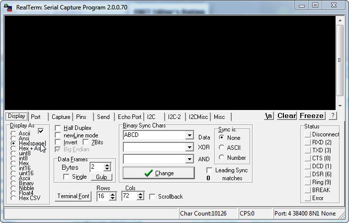
The only important settings here is the ‘Display As’ option. The setting I use the most is “Hex [space]”. This displays the data received as hexadecimal strings (i.e., “00” for a transmission of all 0s’). The ASCII option would display the ASCII-equivalent character for the transmitted hex value (i.e., display “0” for 0x30 - see here for the complete list of ASCII characters). ANSI is similar but somehow different - I’m not sure how. I don’t use most of the other options but I’m sure they’re well-documented in RealTerm’s documentation.
Now is the time to apply power to your microcontroller. If you’ve configured all of the options correctly, when you apply power you should see the sequence “A5 5A A5” displayed in the main window - as seen below:
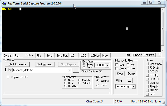
This is a startup sequence that I coded into the microcontroller to indicate that the serial port was properly initialized. If you don’t see this and instead see something else you might have the wrong baud rate selected. If you see nothing at all you might be on the wrong COM port. Play around with the settings while removing and applying power to the microcontroller until you see the startup sequence. That will indicate that all the settings are correct and you’re ready to start receiving accelerometer data from the microcontroller.
To make absolutely sure that all of the settings are configured correctly, click inside the RealTerm data window (shown below) and press ‘0’. This should cause the screen to fill up with data very quickly. In my case it was all “00”’s since my accelerometer wasn’t powered. Depending on what your A/D is hooked up to it could be all 0’s or very small numbers (in the case that it’s measuring noise). Press ‘0’ again to stop the data transfer.
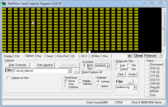
Now you’re ready to save the data to a file that Octave can read.
Select the “Capture” tab and modify the File setting by clicking on the “...” button. This will allow you to select a file to save the accelerometer data in. Once that is populated, click on “Start: Overwrite”. This will create the file in the location you selected and save any data that comes from the microcontroller. Pressing ‘0’ with the focus placed in the data window will start the transmission of data from the microcontroller. You won’t see the data displayed in the data window - it’s going directly to the file. Let it run for a few seconds and then press ‘0’ again to stop the transfer. Then, press the “Stop Capture” button to write the data to the file.
The data is saved as a raw binary and is stored in the file in the order that it comes in. If you open up the resulting file in a hex editor you will see the same hex bytes that RealTerm would display and they would be ordered in the same order they were received in. The important thing to note is that the data is saved exactly as it is transmitted: there is no extra information to use to determine the format of the data or the endianness. This is why it’s so important to have a handle on the idea of endianness and know whether you’re transmitting big or little endian data. Octave is going to process the binary file by reading two bytes at a time and assuming the first one is the low byte. If that assumption is incorrect, the data will be incorrect and it won’t necessarily be obvious.
Now that the data has been saved to a binary file, you can process it and plot it through Octave. Copy the Octave script from the code snippets section into the same directory as that you saved the data in. Then, start Octave and navigate to that directory. When you’re there, type “accel_script” (without quotes). The script interprets the bytes in the file as a series of 16-bit numbers (stored in little-endian fashion of course) and then plots the data graphically. The plot window with the accelerometer data should show up when you run the script. Depending on what’s hooked up to your A/D it may not be very interesting. Below is a plot of A/D readings I got when I hooked an accelerometer up to the A/D and waved the board around a bit.
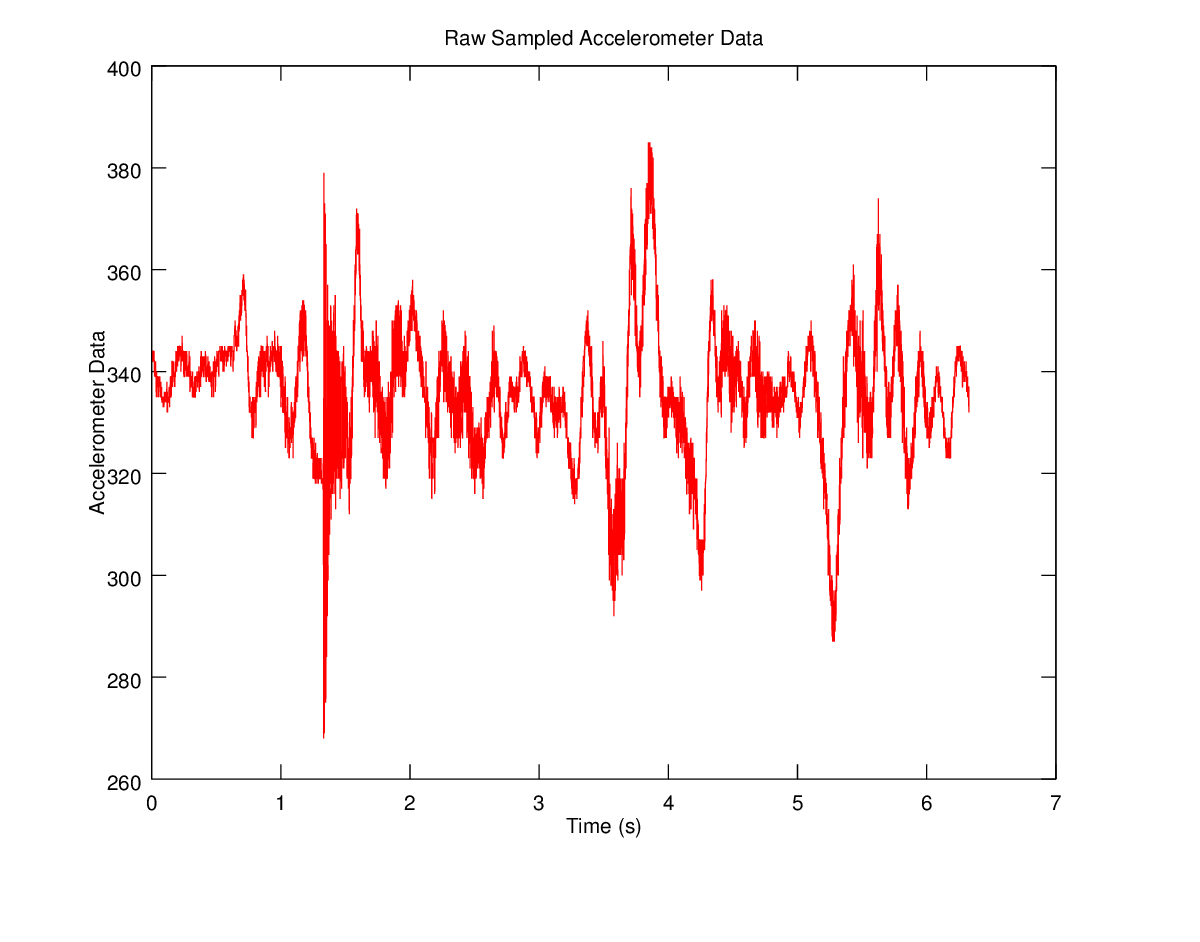
The above data shows the case where every part of the transaction agreed on the endianness of the data. You might be wondering what happens if you confuse endianness - what if you transmit big-endian data when your computer only understands little-endian? You can simulate this by adding “#define BIG_ENDIAN” to the source file and recompiling. That will cause the microcontroller to transmit the data reversed compared to what the PC expects. I reversed the endianness of the data from the microcontroller and then plotted the result - it’s shown below.

The important thing to note is that on the face of it this doesn’t necessarily look wrong - the correct accelerometer data had the same basic shape as this graph. It would be easy to not look too closely at this data and think that it’s correct. However, I know the A/D measurement is only 10 bits. 10 bits can only represent numbers up to 1023, but all of the data is in the range of ~20K. This is much too large for the 10 bit A/D data I should be plotting. If I’m on my toes I can see this and realize that I’ve made a mistake somewhere. If I’m half asleep I won’t notice it at all.
By now you should have a good idea of what endianness is, why it’s important and what basic steps you can take to ensure you respect it when transmitting information between different systems. I hope the code and ideas I’ve presented here save you a bit of time in the future when you’re working with embedded systems. Good luck!


- Comments
- Write a Comment Select to add a comment

Very well written. Walks us through the topic methodically. Nice post.
To post reply to a comment, click on the 'reply' button attached to each comment. To post a new comment (not a reply to a comment) check out the 'Write a Comment' tab at the top of the comments.
Please login (on the right) if you already have an account on this platform.
Otherwise, please use this form to register (free) an join one of the largest online community for Electrical/Embedded/DSP/FPGA/ML engineers:


