


Introduction to Microcontrollers - Interrupts
Quick Links
- Part 1: Introduction to Microcontrollers - Beginnings
- Part 2: Introduction to Microcontrollers - Further Beginnings
- Part 3: Introduction to Microcontrollers - Hello World
- Part 4: Introduction to Microcontrollers - More On GPIO
- Part 5: Introduction to Microcontrollers - Interrupts
- Part 6: Introduction to Microcontrollers - More On Interrupts
- Part 7: Introduction to Microcontrollers - Timers
- Part 8: Introduction to Microcontrollers - Adding Some Real-World Hardware
- Part 9: Introduction to Microcontrollers - More Timers and Displays
- Part 10: Introduction to Microcontrollers - Buttons and Bouncing
- Part 11: Introduction to Microcontrollers - Button Matrix & Auto Repeating
- Part 12: Introduction to Microcontrollers - Driving WS2812 RGB LEDs
- Part 13: Introduction to Microcontrollers - 7-segment displays & Multiplexing
- Part 14: Introduction to Microcontrollers - Ada - 7 Segments and Catching Errors
It's Too Soon To Talk About Interrupts!
That, at least, could be one reaction to this chapter. But over the years I've become convinced that new microcontroller programmers should understand interrupts before being introduced to any complex peripherals such as timers, UARTs, ADCs, and all the other powerful function blocks found on a modern microcontroller. Since these peripherals are commonly used with interrupts, any introduction to them that does not include interrupts is an incomplete introduction, and each peripheral would have to be revisited after the concept of interrupts was finally introduced. That just strikes me as wasteful.
So, let's talk about interrupts. I used to be intimidated by them when I started programming μCs, and maybe you are too. That is very much the wrong attitude - interrupts are not some kind of magic, but just a very powerful and very manageable technique for dealing with all kinds of things that need attention at "unexpected" times.
Consider this scenario. We need to monitor a GPIO input and respond to that input going active within a few microseconds. Not tens of milliseconds as was the case with our human button pushes, but a few microseconds. The μC program could be at any point in its execution when this input goes active. We need to do the equivalent of monitoring this signal not a hundred times per second, but hundreds of thousands of times per second, while still doing all of the other things our program needs to do. How can we possibly respond so quickly, and still have any time to do any other work in our program? Interrupts are the answer.
Now You See It, Now You Don't
An interrupt is a signal (generally called an "interrupt request") to the CPU to immediately begin executing different code, code that is written to respond to the cause of the interrupt. "Immediately" can be as soon as the end of the current instruction, in the best case. The time between the generation of the interrupt request and the entry into the ISR is called the "interrupt latency," and faster (lower latency) is always better. The CPU will remember the location of the next instruction it was going to execute by storing that instruction address in a register or memory location, and will then jump directly to the code designated by the programmer for that particular interrupt. In addition to saving the address of the next instruction, it will often also save the CPU status register and disable further interrupts. It will also, in most cases, automatically clear the interrupt request that triggered the ISR entry, so that a single interrupt request does not result in the ISR being entered multiple times. Occasionally, depending on interrupt type and microcontroller design, it will require user code in the ISR to explicitly clear the interrupt request. It is very important to check the datasheet for a given interrupt source to see if the ISR code must clear the interrupt request, or the uC will just keep re-interrupting on the one interrupt request event forever.
A microcontroller CPU will be designed to respond to a number of different interrupt sources (perhaps 10 to 100 sources, typically), and each source can have specific user-written code which executes when that interrupt triggers. The code that executes for an interrupt is called the "interrupt service routine" or ISR. The "now you see it, now you don't" heading refers to what you would see if you were watching the code execute in slow motion. The program counter would be moving from one instruction to the next, and then when the interrupt triggered the PC would suddenly end up in some totally different area of the program (the entry point of the ISR). Then, when the ISR was complete, the PC would just as suddenly be pointing back to the next instruction, as if nothing had happened.
Interrupts are always off or disabled when coming out of RESET. In fact, they are doubly disabled. Each individual interrupt source is disabled, and also the global CPU interrupt flag is disabled. For an interrupt to happen (to have its ISR run), both the individual interrupt must be enabled, and the CPU global interrupts must be enabled. And finally, of course, the interrupt condition itself must occur e.g. a pin being driven low, or a timer rolling over, or whatever the particular interrupt is triggered by.
It is up to the user program to select which interrupts to enable, and at what points in the program execution to enable them (and once enabled, an interrupt can be disabled again, then re-enabled, as often as needed). The user program will also have an ISR (very similar to a function) for each interrupt that will be enabled, and each of these ISRs will be mapped to its corresponding interrupt source. It is crucial that any interrupt that is enabled, ever, has a valid ISR mapped to it. Otherwise, when the interrupt triggers, the CPU will start trying to execute code in some garbage location AKA in the weeds, and that's the end of that. Or, if you're lucky, the compiler will have supplied an Oops! ISR for all unused interrupts, and with your debugger you'll find the μC looping in that ISR and figure out where you went wrong.
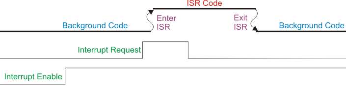
This diagram attempts to show how an interrupt, if enabled, pauses the background code and runs the associated ISR:
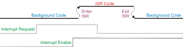
And here is a diagram which shows an interrupt event occuring before the interrupt is enabled, and how the interrupt is only responded to after it is enabled:
Where Are The Return Address And Register Data Saved?
As part of the automatic response to an interrupt request, the uC hardware will save the address of the next instruction that was to be executed. This address is either saved onto the stack (as pointed to by the CPU stack pointer), or it may be saved into a special CPU register, often called the "link register". The AVR uses the hardware stack pointer, while the STM32 uses a link register. Saving to a link register is faster because register-to-register moves are always faster than register-to-memory moves, but when another level of interrupts (or subroutines) is required, the link register must then be saved off to memory by user code (code that is generated by the compiler if you're using a HLL).
As for any register data that is saved and restored, that data will also be saved to a stack - that is, out to memory. That stack may be the stack maintained by the hardware stack pointer, or it may be a stack maintained by software, just as is used for saving off the link register when necessary.
Is an ISR a Function?
As stated, an ISR is similar to a function, but there are some critical differences for most microcontroller designs. Most of these differences revolve around the fact that an ISR must be "invisible" to the background code that was executing when the ISR is run. What this means is that no CPU registers or flags can be altered that the background code may be using. The total state of the CPU, as far as the background code is aware, must be identical when the ISR returns as when the interrupt triggered. So the ISR must save the state of the CPU on entry, and restore that same state on exit.
If using a high level language, the compiler will take care of most or all of this state saving and restoring. The programmer simply has to tell the compiler that the ISR function is an ISR, and what interrupt it maps to, and the compiler will fill in the code details invisibly. The compiler will add the following code to the ISR:
- Before user ISR code, code to save all flags and registers necessary to maintain main code state
- After user ISR code, code to restore all saved flags and registers in correct order
- Finally, a return-from-interrupt instruction which performs any final cleanup such as restoring the saved status register, and returns program execution to the instruction after the interrupted instruction
The compiler will also handle mapping the actual ISR code to the associated interrupt. If writing in ASM the programmer has to write all the state saving and restoring code explicitly, as well as explicitly place the address of the ISR into the appropriate interrupt vector or slot.
Each possible interrupt will have an entry in a region of memory usually called the interrupt table or interrupt vector table. Depending on the CPU design, these entries might contain actual code, or they might be data locations where the starting addresses of the associated ISRs are stored. As it happens, the AVR uses the first form of interrupt table (each interrupt vector location contains a jump to the associated ISR), while the STM32 uses the second form of table (each interrupt vector location contains the address of the associated ISR).
Interrupt vector table entries for interrupts that will never be enabled can either be left empty, or can all be set to point to a dummy ISR that just returns immediately, or can all be set to point to an ISR that somehow logs and reports the unexpected interrupt (was it a hardware glitch? did the programmer forget to write an ISR for an enabled interrupt?).
What Should An ISR Do?
In most cases the answer is, as little as possible. An ISR should do what must be done immediately, but should not do anything that is better left for later, to be done in the background code. Here's an analogy: You're carving an ice sculpture for your whist club when the doorbell rings (interrupt!). You answer the door (start of ISR) and receive the 2000 piece jigsaw puzzle you've ordered. Now, do you sit down and complete the puzzle at this moment? Or do you put the puzzle in a safe place and get back to the sculpture before it melts? Prudence says that you put the puzzle aside and get back to the other work at hand, then come back to the puzzle when you have nothing more pressing to do. The same applies to an ISR. Do what you must in the ISR, and save off any data or state information so that your background code can do the rest of the work at a more appropriate time.
This becomes even more critical when multiple interrupts are enabled, as will usually be the case in an embedded system. Having ISRs that take a long time to run (because they do too much inside the ISR) may cause delayed response to other interrupts that need fast handling.
Who Rang?
In some cases only one event can trigger a given interrupt, so the ISR for that interrupt knows exactly the event that has triggered it. However, in many cases multiple events will all vector to a single ISR. For example, with the STM32 as many as 4 timer events can vector to a single timer ISR (we will see this in the chapter on timers). In these cases the first task of the ISR is to determine which event has caused the interrupt. It will do this by checking the appropriate flags for all the possible interrupting events until it finds the one that has caused the interrupt. Then it will handle that interrupting event in the normal fashion.
Interrupt-Driven LED Program
One form of interrupt that all microcontrollers can respond to is a simple digital change of state on a specified pin (usually called an "external interrupt" pin). For example, if the pin is held high by a pullup resistor, and then is brought low by some signal or action, the high-to-low transition on the pin can trigger an interrupt. We can modify our button-controlled LED program to detect the button transition via interrupt and change the LED accordingly. This will give us a simple introduction to interrupts, and also show why reading buttons with external interrupts is not really a good idea.
Whether you are using an AVR or an STM32, the first step is to look on the chip datasheet to see which pin or pins supports external interrupts. For the STK-500 with the ATmega8515, there are three such pins, PD2, PD3 and PE0, so we will choose to connect the 8 buttons of the STK-500 to PORTD, and use either button 2 or button 3 - let's choose button 2 (PD2) which is external interrupt INT0. For the STM32VLDiscovery board, we only have one button, wired to PA0. It turns out that the STM32 device is very flexible and almost any GPIO can be used as an external interrupt, so our button on PA0 will be fine.
External Interrupt Type And Polarity
There are a few different ways that an external interrupt can be configured, depending on what the particular microcontroller allows. In the first place, external interrupts can be edge-triggered or level-triggered. An edge-triggered interrupt generates an interrupt request only on an edge - that is, when the interrupt line goes from one state to the opposite state (1->0 or 0->1). A level-triggered interrupt generates an interrupt request whenever the interrupt line is in the active state, so for example a low-level-trigger interrupt will generate requests whenever the line is low, and (this is important), will continue to generate requests until the line is brought high. If the software or the hardware is incorrectly designed, a single level-triggered interrupt could result in a furious cycle of interrupt..end interrupt..re-enter interrupt..end interrupt and so on, thousands or millions of times per second.
The second aspect of an external interrupt is the interrupt polarity. For an edge-triggered interrupt, the polarity could be rising edge triggered (0->1) or falling edge triggered (1->0). For a level-triggered interrupt, the polarity could be low triggered (whenever the input is 0) or high level triggered (whenever the input is 1). Again, these are possible configuration options, but not every external interrupt input on every microcontroller will support all of these options. It is even possible to have an external interrupt input that triggers on any logic change - that is, it will generate an interrupt request on a high-low transition (1->0), or on a low-high transition (0->1). This is just an edge-triggered interrupt that triggers automatically on both possible edges rather than just on one specified edge.
Note as well that the distinction between edge-triggered and level-triggered interrupts is a fundamental distinction for all types of interrupts, not just external interrupts.
Configuring Interrupts
In the general case, configuring a particular interrupt requires taking a good look at the chip data sheet. For external interrupts on fixed pins things are easier than the more configurable interrupts on parts like the STM32. The AVR INT0 interrupt only requires us to select the interrupt polarity and enable the interrupt. AVR INT0 can be configured for rising-edge, falling-edge, both-edge, or low-level triggering. Remembering that STK-500 buttons are active low, we will choose falling-edge so as to be able to catch the initial button push (otherwise we would have to wait until the button was released before an interrupt was generated). Looking at our AVR datasheet we see that we need to set bits ISC01/ISC00 in register configuration MCUCR to 1/0 for negative-edge trigger. Now we need to enable the INT0 interrupt, so we need to set bit INT0 in interrupt enable register GICR. At this point, if global interrupts are enabled, the CPU will respond to any negative-edge input on INT0. What's more, if there was a previous edge that set the internal INT0 flag, that previously set flag would now generate an interrupt. This is almost always a bad thing, generating an interrupt off a previously set flag, so we need to do one other thing before enabling the interrupt. We need to write a '1' to bit INTF0 in interrupt flag register GIFR. Writing a '1' clears any pending INT0 interrupt, which is what we want to do before enabling the interrupt. So our full AVR configuration is as follows:
MCUCR = 0b10 << ISC00;  // negative edge trigger
GIFR = 1 << INTF0;	// clear any pending interrupt
GICR = 1 << INT0;	// enable INT0
The ISR
Now it's time to write the interrupt service routine. For the AVR, a negative edge means the button has just been pushed, so we want to turn the LED ON. Likewise, a positive edge means the button has been released and we want to turn the LED OFF. But wait, we've only configured for a negative edge, how will we detect a positive edge. This is actually pretty simple. Inside the ISR, if the interrupt is configured for negative edge, reconfigure it for positive edge. If configured for positive edge, reconfigure for negative edge. In the same code branches that reconfigure the interrupt, turn the LED ON or OFF depending on which edge has brought us into the ISR this time.
Marking the ISR as an ISR, and mapping it to the INT0 vector, is very compiler dependent as was mentioned. For Atmel Studio's version of the gcc compiler, it will look like this:
ISR(INT0_vect)
{
   // ISR code here
}
The Final Program - AVR
Here is the full program, with the configuration and ISR as discussed above, and the global interrupt enable just before entering the forever loop. The ISR alternates the next interrupt edge and turns the LED on or off according to the edge that just caused the interrupt. As discussed above, when the ISR is entered the interrupt request is automatically cleared by the hardware, so there is no code required in the ISR for this task.
To simulate background code doing its own thing, the program has our old LED Blinky loop running. Thus in action you will see one LED blinking via the background code, and another turning on and off via the button interrupt.
// AVR_INT1
// Blink LED on PB0
// Control LED on PB1 via
// button interrupt on PD3

#include <avr/io.h>
#include <avr/interrupt.h> // bring in interrupt stuff

ISR(INT0_vect)             // tell compiler this ISR is for INT0 (PD2)
{
  if (MCUCR & (1<<ISC00))  // true if pos. edge trigger
  {
    PORTB |= (1<<PB1);     // LED 1 OFF
    MCUCR &= ~(1<<ISC00);  // set to neg. edge trigger
  }
  else                     // neg. edge trigger
  {
    PORTB &= ~(1<<PB1);    // LED 1 ON
    MCUCR |= (1<<ISC00);   // set to pos. edge trigger
  }
}

void delay(volatile uint32_t d)
{
  while (d-- != 0)
    ;
}

int main(void)
{
  DDRB = (3<<PB0);         // LED output on PB0, PB1
  PORTB = (3<<PB0);        // start with LEDs OFF

  MCUCR = 0b10<<ISC00;     // negative edge trigger
  GIFR = 1<<INTF0;         // clear any pending interrupt
  GICR = 1<<INT0;          // enable INT0

  sei();                   // enable all interrupts

  while(1)
  {
    PORTB ^= (1<<PB0);	 // toggle LED 0 in the background
    delay(80000);
  }
}
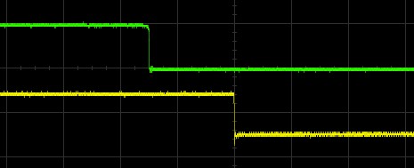
This scope image shows the delay between the interrupt-triggering button push (green) and the LED output inside the ISR (yellow) with the above program running. The timescale is 2us / division, so the response time from external input to ISR output is only about 3 microseconds (with the AVR running at 8 MHz):
The Final Program - STM32
Once again, the STM32 version of this program is fundamentally the same as the AVR version. What is different is mostly the required interrupt configuration and ISR declaration. Since the STM32 external interrupt capacity is so customizable, it requires more initialization than the AVR. Regarding the ISR declaration, the ARM Cortex M family is rather unique in that it is designed so that regular functions can be ISRs. This is possible because the Cortex M design automatically saves all the status and register data necessary before entering an ISR, and restores it all at the end of the ISR. That is, the Cortex M does automatically all the housekeeping that requires additional ISR code in most other designs. Thus our ISR is just a normal function, without any additional ISR code, which is given the proper name for the EXTI0 interrupt so that it overrides the weak declaration in the startup code. That may be a bit advanced, so just know that it is enough to name the ISR the correct name - I'm sure it's in the documentation somewhere, but I just looked at the startup files to find the correct name. Being able to look into your compiler startup files is a big advantage, and you should not be afraid to poke around in them.
Also note that, unlike the AVR, the STM32 requires that the interrupt request be explicitly cleared inside the ISR.
// STM32_INT1
// Blink LED on PC9
// Control LED on PC8 via
// button interrupt on PA0

#include <stm32f10x.h>

void EXTI0_IRQHandler(void)     // ISR is just a regular function with correct name
{
  if (EXTI->RTSR & 1)           // was set for positive edge
  {
    GPIOC->ODR |= (1<<8);       // set blue LED
    EXTI->RTSR = 0;
    EXTI->FTSR = 1;             // set for negative edge
  }
  else  // was set for negative edge
  {
    GPIOC->ODR &= ~(1<<8);      // clr blue LED
    EXTI->FTSR = 0;
    EXTI->RTSR = 1;             // set for positive edge
  }
  EXTI->PR = 1;                 // clear this interrupt flag
}

void delay(volatile uint32_t d)
{
  while (d-- != 0)
    ;
}

int main(void)
{
  RCC->APB2ENR |= RCC_APB2ENR_IOPAEN; // enable PORTA for button input
  GPIOA->CRL = (0b0100);              // CNF=1, MODE=0 (floating input)

  RCC->APB2ENR |= RCC_APB2ENR_IOPCEN; // enable PORTC for LED output
  GPIOC->CRH = 0b0010 | (0b0010<<4);  // CNF=0, MODE=2 (2MHz output) (PC8,PC9)

  AFIO->EXTICR[0] = 0;                // EXTI0 is PA0
  EXTI->RTSR = 1;                     // rising edge, EXTI0
  EXTI->IMR = 1;                      // enable EXTI0
  NVIC->ISER[0] = (1 << EXTI0_IRQn);  // enable EXTI0 in NVIC

  while (1)
  {
    GPIOC->ODR ^= (1<<9);             // toggle green LED
    delay(80000);
  }
}
Interrupts Can't Be That Simple, Right?
Right. There are a lot of details and gotchas left to discuss regarding interrupts. For example, our interrupt programs above are both garbage, actually - that is, they can give the wrong results on occasion. You may even notice that the LED occasionally seems to miss a button push. But they're good enough to show you how interrupts work, and to provide a foundation for further work with them. The next tutorial chapter will go into some of the most important details and gotchas, including what is wrong with our interrupt programs and how to fix them. After that we'll start looking at timers, one of the most useful of all microcontroller peripherals, but one that pretty much requires interrupts to be used effectively.


- Comments
- Write a Comment Select to add a comment
http://www.npeducations.com
interrupt INT0 is on PD2 (not PD3)

Thanks for tutorial
To post reply to a comment, click on the 'reply' button attached to each comment. To post a new comment (not a reply to a comment) check out the 'Write a Comment' tab at the top of the comments.
Please login (on the right) if you already have an account on this platform.
Otherwise, please use this form to register (free) an join one of the largest online community for Electrical/Embedded/DSP/FPGA/ML engineers:


