


Introduction to Microcontrollers - Buttons and Bouncing
Quick Links
- Part 1: Introduction to Microcontrollers - Beginnings
- Part 2: Introduction to Microcontrollers - Further Beginnings
- Part 3: Introduction to Microcontrollers - Hello World
- Part 4: Introduction to Microcontrollers - More On GPIO
- Part 5: Introduction to Microcontrollers - Interrupts
- Part 6: Introduction to Microcontrollers - More On Interrupts
- Part 7: Introduction to Microcontrollers - Timers
- Part 8: Introduction to Microcontrollers - Adding Some Real-World Hardware
- Part 9: Introduction to Microcontrollers - More Timers and Displays
- Part 10: Introduction to Microcontrollers - Buttons and Bouncing
- Part 11: Introduction to Microcontrollers - Button Matrix & Auto Repeating
- Part 12: Introduction to Microcontrollers - Driving WS2812 RGB LEDs
- Part 13: Introduction to Microcontrollers - 7-segment displays & Multiplexing
- Part 14: Introduction to Microcontrollers - Ada - 7 Segments and Catching Errors
What Is A Button?
To your hardware, that is. As discussed in Introduction to Microcontrollers - More On GPIO, a button (or key, or switch, or any form of mechanical contact) is generally hooked up to a microcontroller so as to generate a certain logic level when pushed or closed or "active," and the opposite logic level when unpushed or open or "inactive." The active logic level can be either '0' or '1', but for reasons both historical and electrical, an active level of '0' is more common. Here is the basic button connection to a GPIO input, which we saw in the earlier tutorial chapter:
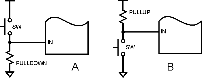
When the switch is open, the pullup or pulldown causes the GPIO input pin to see the inactive logic state, but when the switch is closed it overrides the resistor and causes the GPIO input pin to see the active logic state. As a reminder, drawing 'A' shows an active-high button, while drawing 'B' shows an active-low button.
What Does A Button Look Like?
To your code, that is. The simplest way to represent a button is as a boolean, or as a single zero or non-zero byte. One button, one byte. Call this Method 1, or the Boolean-per-Button method. It's simple because there is no masking required, either in setting the variable or in reading it. The drawback of this approach is that it makes it difficult to check for all the different button possibilities in your system (16 buttons = 16 bytes to test).
Another way to represent a button is as a boolean which is is one bit of a byte or 16-bit word. Now you can have a single byte or word that can hold the state of up to 8 or 16 completely independent buttons (or 32 if you want to go to a 32-bit value). This button aggregate is easy to process in a "switch" statement, and it also provides the ability to check for multiple simultaneous button pushes. By "independent" buttons we mean buttons that can be pressed and recognized regardless of the state of any of the other buttons. This situation or requirement is actually much more common for switches than for buttons, but remember we are treating switches and buttons and keys all the same here. Call this Method 2, or the Bit-per-Button method.
Finally, one can represent the state of multiple non-independent buttons as a single value. Take a calculator keyboard for example. With a calculator there is probably only one keypress allowed at any given time, so a calculator with 20 or 30 buttons can represent all the possible valid button pushes with a single variable that can hold 20 or 30 values. In this case, 30 buttons can be represented by only 5 bits, since the buttons are not independent and thus most (or even all) combinations of multiple buttons are illegal. Call this Method 3, or the Single-Value method.
For the most part, all the examples in this tutorial section will represent buttons according to methods 2 or 3 - that is, as an 8 or 16-bit variable that either represents multiple independent buttons or that represents a unique value among non-independent buttons.
Button Debouncing, Revisited
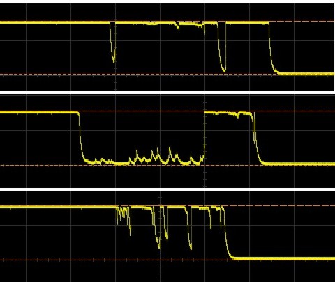
You may remember in Introduction to Microcontrollers - More On GPIO that we saw some scary scope images of switch bounces. Every system that uses any kind of mechanical switch must deal with the issue of debouncing. The key task is to make sure that one mechanical switch or button action is only read as one action by the microcontroller, even though the microcontroller will typically be fast enough to detect the unwanted switch bounces and treat them as separate events. Bouncing can be eliminated by special ICs or by RC circuitry, but in most cases debouncing is done in software because software is "free." (a software person should always carry tomatoes to throw at this point)
Scary images of switch bouncing, redux:
The key to debouncing is to establish a minimum criterion for a valid button push, one that can be implemented in software. This criterion must involve differences in time - two button presses in 20ms must be treated as one button event, while two button presses in 2 seconds must be treated as two button events. So what are the relevant times we need to consider? They are these:
- Bounce time: most buttons seem to stop bouncing within 10ms
- Button press time: the shortest time a user can press and release a button seems to be between 50 and 100ms
- Response time: a user notices if the system response is 100ms after the button press, but not if it is 50ms after
Combining all of these times, we can set a few goals
- Ignore all bouncing within 10ms
- Provide a response within 50ms of detecting a button push (or release)
- Be able to detect a 50ms push and a 50ms release
The simplest debouncing method is to examine the keys (or buttons or switches) every N milliseconds, where N > 10ms (our specified button bounce upper limit) and N <= 50ms (our specified response time). This is the method we used in the last chapter with our example cyclic executive program STM32_LCD2. We then have three possible outcomes every time we read a button:
- We read the button in the solid '0' state
- We read the button in the solid '1' state
- We read the button while it is bouncing (so we will get either a '0' or a '1')
Outcomes 1 and 2 pose no problems, as they are what we'd always like to happen. Outcome 3 also poses no problem because during a bounce either state is acceptable. If we have just pressed an active-low button and we read a '1' as it bounces, the next time through we are guaranteed to read a '0' (remember, the next time through all bouncing will have ceased), so we will just detect the button push a bit later. Otherwise, if we read a '0' as the button bounces, it will still be '0' the next time after all bouncing has stopped, so we are just detecting the button push a bit earlier. The same applies to releasing a button. Reading a single bounce (with all bouncing over by the time of the next read) will never give us an invalid button state. It's only reading multiple bounces (multiple reads while bouncing is occurring) that can give invalid button states such as repeated push signals from one physical push.
So if we guarantee that all bouncing is done by the time we next read the button, we're good. Well, almost good, if we're lucky...
Noise, We Don't Have No Stinking Noise!
Don't we? Well, maybe we don't. Or maybe we do. Sometimes. Microcontrollers often live among high-energy beasts, and often control the beasts. High energy devices make electrical noise, sometimes great amounts of electrical noise. This noise can, at the worst possible moment, get into your delicate button-and-high-value-pullup circuit and act like a real button push. Oops, missile launched, sorry!
If the noise is too intense we cannot filter it out using only software, but will need hardware of some sort (or even a redesign). But if the noise is only occasional, we can filter it out in software without too much bother. The trick is that instead of regarding a single button 'make' or 'break' as valid, we insist on N contiguous makes or breaks to mark a valid button event. N will be a factor of your button scanning rate and the amount of filtering you want to add. Bigger N gives more filtering. The simplest filter (but still a big improvement over no filtering) is just an N of 2, which means compare the current button state with the last button state, and only if both are the same is the output valid.
Note that now we have not two but three button states: active (or pressed), inactive (or released), and indeterminate or invalid (in the middle of filtering, not yet filtered). In most cases we can treat the invalid state the same as the inactive state, since we care in most cases only about when we go active (from whatever state) and when we cease being active (to inactive or invalid). With that simplification we can look at simple N=2 filtering (representing buttons using Method 2), reading 4 buttons wired active-low to AVR PC0-PC3:
u8 filter_buttons_N2(void)
{
  static u8 last_buttons = 0;  // up to 8 buttons, all inactive
  u8 raw_buttons;
  u8 filtered_buttons;

  raw_buttons = ~PINC & 0x0f;  // read 4 buttons (PINC is active-low), active state = '1'
  filtered_buttons = raw_buttons & last_buttons;  // N=2 filtering
  last_buttons = raw_buttons;  // save for next filtering
  return filtered_buttons;     // only active if active this time and last time
}
The function filter_buttons_N2() must be called no more often than our debounce time (10ms). Typically it would be called every 10-25ms. Each time it reads the 4 active-low buttons on PINC, inverts them to active-high, and filters them by ANDing them with the last reading. Only if both readings had a given button high (pressed) will the result be high (pressed). Note that we can filter up to 8 buttons at a time, one per bit position, with this method (16 if we used u16 button variables).
To expand to greater filtering (larger N), keep in mind that the filtering technique essentially involves reading the current button state and then either counting or reseting the counter. We count if the current button state is the same as the last button state, and if our count reaches N we then report a valid new button state. We reset the counter if the current button state is different than the last button state, and we then save the current button state as the new button state to compare against the next time. Also note that the larger our value of N the more often our filtering routine must be called, so that we get a filtered response within our specified 50ms deadline. So for example with an N of 8 we should be calling our filtering routine every 2 - 5ms, giving a response time of 16 - 40ms (>10ms and <50ms).
The details of the filtering depend on whether the value to be filtered is a simple binary (a single button), or is a multi-value variable such as the state of a button matrix. If the value is a simple binary, we can do some tricks with bit-shifting to find our N consecutive states. For simplicity, let us first choose N to be 8 or 16 or 32 - that is, the number of bits in a u8, u16 or u32. Let's choose a u8 for this example. Now, every time we sample the button state, we simply shift that state into a u8 "accumulator" variable. Thus the u8 variable will maintain the last 8 button samples. When the variable contains 0b00000000 then we have 8 contiguous 0s, and we have a valid filtered '0' output. Similarly, when the variable contains 0b11111111 then we have a valid filtered '1' output. Any other value is indeterminate. So all we have to do is shift the current state into the variable and compare for 0 or ~0 (remember that the '~' operator is the bitwise inversion operator). Thus ~0 is ~0b00000000 is 0b11111111. OK, to be more correct, (u8)~0 is 0b11111111. Since we are now using an entire byte (or word) to represent one button, this is a variant of Method 1. In this case our button is assumed to be active-low, wired to PC3.
u8 filter_button_N8(void)
{
  static u8 button_acc = 0;   // start with valid inactive

  button_acc <<= 1;           // shift out oldest state, make new state a 0
  if (~PINC & (1<<3))
    button_acc |= 1;          // button on PC3 is active (low), shift in a 1
  return button_acc;          // 0 is inactive, ~0 is active, others indeterminate
//
//return (button_acc == ~0) ? 1 : 0; // alternately, return 1 for active, 0 otherwise
//
}
But I Want An N Of 5!
N values of 8, 16 or 32 are especially easy to deal with, but they may not fit in with your timing constraints; especially, your timer tick rate. That's OK, since other N values are also useable. For example, let's choose an N of 5. That means we want to use the last 4 inputs along with the current input in our filtering. If we were to use the method described above, we would have a valid filtered '0' with the byte 0bxxx00000, and a valid filtered '1' with the byte 0bxxx11111. Hmm, those 'x's are a problem, but not a big one. We have two approaches to deal with them. We can either just AND off those bits and compare to 0b00000 or 0b11111, or we can stuff in more bits every time we read the button state and continue to compare with 0 or ~0 to look for a valid filtered input. Using the latter approach in our N=5 example, instead of adding a single bit into the accumulating variable, we'll add 4 bits - 0b0000 if the current button state is '0', or 0b1111 if the current button state is '1'. The general rule is to add in 8-N+1 bits of all 0s or all 1s. This even works for N=1 - we would then add 0b11111111 or 0b00000000, which is just the 0 or ~0 that we will compare with.
By the way, there's a simple way to define the values we will AND or OR to our accumulator variable, based on the value of N. This is one application of the useful pattern (1<<X)-1, which will give a value or mask of all '1's in the rightmost (least significant) X bits.
#define BUTTON_VAL ((1<<(8-N+1)-1) // for N=5, this is 0b00001111
Now our input and filtering routine looks like this:
#define N           5
#define BUTTON_VAL  ((1<<(8-N+1))-1)  // for N=5 this is 0b00001111

u8 filter_button_N5(void)
{
  static u8 button_acc = 0;   // start with valid inactive

  button_acc <<= 1;           // shift out oldest state
  if (~PINC & (1<<3))
    button_acc |= BUTTON_VAL; // button on PC3 is active (low), load in 1s
  else
    button_acc &= ~BUTTON_VAL;  // button is inactive (high), load in 0s
  return button_acc;          // 0 is inactive, ~0 is active, others indeterminate
//
// return (button_acc == ~0) ? 1 : 0; // alternately, return 1 for active, 0 otherwise
//
}
Expanding This Filter Method To Multiple Independent Buttons
As you can see above, the bit-shift filter method can only deal with one button at a time (in our examples, we hardwired that button to be PC3). Of course in the usual case we want a more general ability to filter multiple buttons. To do this we can create suitable data structures that encapsulate all the necessary data for a given button, and pass in the associated structure to a filter program for each button.
typedef struct
{
  u8  b_num;  // the bit position of this button on our button port
  u8  b_acc;  // the button accumulator
  u8  b_val;  // the boolean button val (active or other)
} B_DATA;

u8 filter_button_N8(B_DATA * p_bd)
{
  p_bd->b_acc <<= 1;          // shift out oldest state, make new state a 0
  if (~PINC & (1<<p_bd->b_num))
  p_bd->b_acc |= 1;           // button on PC3 is active (low), shift in a 1
  return p_bd->b_acc;         // 0 is inactive, ~0 is active, others indeterminate
  //
  //p_bd->b_val = (p_bd->b_acc == ~0) ? 1 : 0;
  //return (p_bd->b_val; // alternately, return 1 for active, 0 otherwise
  //
}
Here we are still hard-wiring the button port (PINC), but not the bits within the port. We can now maintain an array of B_DATA structures, one for each button, and filter all the buttons in a loop.
#define NUM_B 6
B_DATA Button_data[NUM_B]  // elements must be initialized before use

void filter_all_buttons_N8(void)
{
  u8 i;

  for (i = 0; i < NUM_B; i++)
    filter_button_N8(&Button_data[i]);  // results are in b_acc and b_val for each i
}
We can also collect all of our filtered buttons into a button byte or word (Method 2) if we like. Here we have altered filter_button_N8() to return a '1' if the filtered button is active and a '0' otherwise, to make our bit shifting easier:
u8 filter_button_N8(B_DATA * p_bd)
{
  p_bd->b_acc <<= 1;          // shift out oldest state, make new state a 0
  if (~PINC & (1<<p_bd->b_num))
  p_bd->b_acc |= 1;           // button on PC3 is active (low), shift in a 1
  p_bd->b_val = (p_bd->b_acc == ~0) ? 1 : 0;
  return p_bd->b_val;         // return 1 for active, 0 otherwise
}

u8 filter_all_buttons_N8(void)
{
  i8 i;
  u8 b;
  u8 buttons = 0;

  for (i = NUM_B - 1; i >= 0; i--)  // notice reverse count order, to accomodate left shift
  {
    b = filter_button_N8(&Button_data[i]); // results are in b_acc and b_val for each i
    buttons = (buttons << 1) | b;          // b must be 0 or 1
  }
  return buttons;
}
When Does A Button Press End?
It's pretty clear when a button press begins, but when does it end? Imagine a perfect button - no bouncing, no noise. This button is in a vending machine, and pressing the button once is intended to cause the machine to deliver one can of Tazmanian Cola:
// assume buttons filtered and checked every 50ms
u8 buttons = filter_buttons();  // GPIO, filtering details don't matter

if (buttons == DISPENSE_TASMANIAN_COLA_BUTTON)
  dispense_tasmanian_cola();
So how many cans of Tasmanian Cola will you get? Trust me, you had better be very thirsty if you're using this vending machine, because you'll get 20 cans per second for as long as you hold down the button!
The problem is that the software is looking to see if the button is pressed (looking at the button state), when it should be looking to see if the button has been pressed once (looking at a button event). The difference is critical. The button state just is what it is, but a button event must be consumed when used so as not to deceive the code into thinking the multiple button events have occurred. In this, buttons (and keys) are different from switches, where it is generally the state that one is interested in.
To turn button pushes into button events we need to think in terms of button flags. A flag will be set when a button push occurs, and cleared when that button push is consumed - that is, when acted on by the software. Note carefully that the flag is not set whenever the button is found to be pushed (active), but only when the button is first pushed (first goes active - the "leading edge" of the button push). We will revisit this restriction when we look at auto-repeating, but for now we will hold to this restriction. But for now:
- Flag is set when button goes from inactive or indeterminate, to active
- Flag is cleared when software consumes - that is, acts upon - the button
Let's assume a byte of filtered buttons using Method 2:
//
// detect button events
//
u8 buttons;             // raw filtered buttons
u8 new_buttons;         // all buttons that just went from 0 to 1
u8 last_buttons = 0;    // last raw active buttons
u8 button_flags = 0;    // all buttons that have gone active

buttons = get_filtered_buttons();
new_buttons = buttons & ~last_buttons;  // 1s for each button that went from 0 to 1
button_flags |= new_buttons;        // add all new button pushes to existing pushes
last_buttons = buttons;             // for next time thru

//
// consume a button event
//
if (button_flags & (1<<MY_BUTTON))  // detect MY_BUTTON event
{
  button_flags &= ~(1<<MY_BUTTON);  // consume MY_BUTTON event
  ..process MY_BUTTON..
}
Buttons In Combination
So far we have been looking at button event data as being Method 1 or Method 2 data (that is, independent booleans), but this is often not the case. Many times, such as with a keypad or keyboard, we want a single code or value to represent all of the buttons being pressed. This also makes debouncing easier because we are just debouncing one value at a time, not N different buttons.
For now let's just assume a 16-button keypad and a scanning routine that returns a raw value from the button or buttons being pushed on the keypad. Let's also specify an example encoding:
- 0: 1
- 1: 2
- 2: 3
- 3: 4
- 4: 5
- 5: 6
- 6: 7
- 7: 8
- 8: 9
- 9: 10
- EQUAL: 11
- CLEAR: 12
- +: 13
- -: 14
- *: 15
- /: 16
- No key pushed: 0
So these are the values returned by read_keypad() below, and thus by filter_keypad(). This is a pretty simple calculator keypad, without, for example, any decimal capability, but it will demonstrate the techniques. We will stipulate some function read_keypad() which reads the keypad buttons and returns one of the values specified above. Now how do we debounce this? We will look for N contiguous identical keypad values, just as we have been doing up to now. Only the method will be a bit different.
u8 filter_keypad(void)
{
  static u8 last_val = 0;           // 0 means no buttons pushed
  static u8 count = 0;              // debounce filter count
  u8 val;                           // raw val this time
  u8 filtered_val = 0;              // our filtered return val

  val = read_keypad();              // get raw keypad value
  if (val != 0)                     // have a keypad button push
  {
    if (val == last_val)            // we're filtering this val
    {
      if ((count != 0) && (--count == 0))  // continue filtering & check if done
      {
        filtered_val = val;         // found enough consecutive values to return as valid
      }
    }
    else
    {
      count = FILTER_COUNT;         // start filtering a new val
    }
  }
  last_val = val;
  return filtered_val;
}
As with all the other button filtering methods, this method will be called once every filtering interval, which might be 1-10ms. The first check (if (val != 0)) checks for any button pushes. If none, the no-button-value of 0 is returned. The second check looks to see if the new value is the same as the last value. If it is then we are in the midst of filtering the value. If not (if a new val is detected) the filter count is loaded to its full filter value and filtering begins for the new value. The third check (if we are in the midst of filtering) looks to see if the filter count has just been decremented to zero. If so, the code reports this value as the filtered val, but will not continue to report it in subsequent passes.
This method offers a few bonuses that may not be readily apparent. In the first place, it returns true keypad events. It will return the filtered keypad value only once (when count decrements from 1 to 0), as is desired, and will not continue to return it as buttons remain held down. In the second place, and related to the first, it allows us to add auto-repeat very easily, as we will see in the next tutorial chapter. Also in the next tutorial chapter we will look at matrixed buttons and how to scan the matrix to read them.


- Comments
- Write a Comment Select to add a comment
Thanks a lot Mike...

thanks for this great article. it contains very useful and practical information.
To post reply to a comment, click on the 'reply' button attached to each comment. To post a new comment (not a reply to a comment) check out the 'Write a Comment' tab at the top of the comments.
Please login (on the right) if you already have an account on this platform.
Otherwise, please use this form to register (free) an join one of the largest online community for Electrical/Embedded/DSP/FPGA/ML engineers:


