


Introduction to Microcontrollers - Button Matrix & Auto Repeating
Quick Links
- Part 1: Introduction to Microcontrollers - Beginnings
- Part 2: Introduction to Microcontrollers - Further Beginnings
- Part 3: Introduction to Microcontrollers - Hello World
- Part 4: Introduction to Microcontrollers - More On GPIO
- Part 5: Introduction to Microcontrollers - Interrupts
- Part 6: Introduction to Microcontrollers - More On Interrupts
- Part 7: Introduction to Microcontrollers - Timers
- Part 8: Introduction to Microcontrollers - Adding Some Real-World Hardware
- Part 9: Introduction to Microcontrollers - More Timers and Displays
- Part 10: Introduction to Microcontrollers - Buttons and Bouncing
- Part 11: Introduction to Microcontrollers - Button Matrix & Auto Repeating
- Part 12: Introduction to Microcontrollers - Driving WS2812 RGB LEDs
- Part 13: Introduction to Microcontrollers - 7-segment displays & Multiplexing
- Part 14: Introduction to Microcontrollers - Ada - 7 Segments and Catching Errors
Too Many Buttons, Not Enough Inputs
Assigning one GPIO input to each button can use up a lot of GPIO pins. Numeric input requires at least 10 buttons, plus however many additional control or function buttons. This can quickly get expensive, GPIO pin-wise, and also connector-wise if the keypad is off the uC PCB as it often would be. A very common response to this expense is to wire buttons (keys, etc) in a matrix. By connecting our buttons in an R by C matrix, we can read as many as R*C buttons using just R+C GPIO lines. For our docking board 4x4 button matrix we require 4 output pins and 4 input pins, for a total of 8 pins to read 16 buttons. Here is a schematic of a 4x4 button matrix:
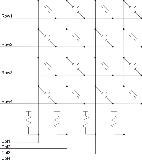
In this schematic, our GPIO outputs are connected to the rows, and our inputs are connected to the columns. This could, of course, be reversed, with the pulldown/pullup resistors being moved to stay connected to the input lines. Nor does the layout of the buttons need to be a square or rectangle - it can be any conceivable layout. Schematics are not mechanical drawings. Finally, while we have shown pullup resistors here, they could just as easily be pulldown resistors. I used pullups because both the STM32 and the AVR have built-in pullups (the STM32 also has built-in pulldowns, but not so the AVR). This means that our active state or level will be '0' and our inactive state or level will be '1'.
So how does this all work? Well, with no button pushed (closed), all of our inputs are pulled up to 1 (or down to 0, if using pulldowns). Now suppose the user pushes the top left button. Columns 2-4 still remain pulled up to 1, but now column 1 is directly connected to row 1. If row 1 is either open (set as an input) or is an output set to '1', column 1 will be a 1 and indistinguishable from when the button is not pushed. But if row 1 is an output set to '0', column 1 will be a 0. If we know that we are driving row 1, and only row 1, to a '0', and we read a 0 on column 1 and only on column 1, we can identify that the top left button is being pushed.
So the way to read a button matrix is to drive one row at a time to the active level (the opposite polarity of the pullup/pulldown resistors), and read all the input columns, looking to see if any column is at the active level. Then switch to the next row, and so on forever. This is commonly called scanning the matrix. If we find a column at active level, we stop the matrix scan and generate a key event - typically we would number the event as (Column + (Row * NUM_COLS)) or (Row + (Column * NUM_ROWS)) (either calculation is acceptable). This encodes button event in the range 0 to R*C-1, assuming both Row and Column are counted up from 0. Since it is common to want to reserve the 0 value as meaning no event (no buttons pushed), we can add 1 to the event number to get events in the range 1 to R*C.
What do we do with the rows we are are not driving active? We have two choices, as mentioned above. We can drive them to the inactive level, or we can set them as inputs and let the pullups/pulldowns drive the columns to the inactive level. If we drive them to the inactive level, we have the possibility that 2 keys are pressed at the same time such that the active row output is connected directly to an inactive row output. This is not a good thing, but in my experience outputs can handle this condition briefly. A better hardware design in this case is to add low-value resistors (say 200 Ohms) in series with each row line, which eliminates the possiblity of a dead short between outputs. Otherwise, set the inactive row pins to inputs and then there can never be two outputs shorting together since there can never be two outputs enabled, only one. So the choices are (a) do nothing and trust that the outputs can handle brief shorts, or (b) add small resistors in the row lines, or (c) only set one row pin to output at a time.
Too Fast Is Not Too Good
It's easy to forget that the world doesn't react instantaneously to our programs. Without thinking about the time scale involved, we may set a row output high in one instruction and read the column inputs in the next instruction some 50 or 100ns later, and expect to get a valid input. The problem is, the world is full of parasitic Rs and Cs and Ls, and signals don't change instantly. If you have a pullup of 50kOhms and a parasitic capacitance of 10pf, that's an RC time constant of 500ns, meaning your pullup is not going to produce a valid '0' until about 1/2 microsecond, or perhaps 5-50 instructions, later. It's important to remember just how fast our microcontrollers are, and to make sure we set outputs and switch inputs well before we expect to read valid inputs. We'll see the same issue when switching ADC input channels, for example. Plan ahead in your code layout to give your inputs plenty of time to settle to their correct values before reading them. This typically involves rearranging code so that the outputs are set before a delay (maybe just the execution of some housekeeping code) or before leaving an ISR, and then the inputs are read at the end of the delay or at the beginning of the next triggering of the ISR.
Scanning A Keypad
So now we get down to some code. The hardware has 16 buttons in 4 rows by 4 columns, as shown in the drawing above, but any number of rows and columns can be used depending on how many buttons must be read.
As per the drawing above, we will use pullup resistors on the input columns - in particular, the pullup resistors built in to both the AVR and STM32 families of microcontrollers. Each row in turn will be driven low, and all columns will be scanned for a low input (a '1' after inverting the column data).
Note finally that no debounce filtering is done in the keypad scan routine. That is left to another routine, which just calls the keypad scan routine to get the raw button data which it then filters.
This code is for AVR, but the STM32 code will only have minor differences in GPIO setup and access.
#define KP_ROW_PORT   PORTC
#define KP_ROW_DDR    DDRC    // row lines on port C
#define KP_COL_PORT   PORTC
#define KP_COL_DDR    DDRC    // col lines on port C
#define KP_COL_PIN    PINC

#define KP_ROWS       4
#define KP_COLS       4

#define KP_FIRST_ROW  4       // rows are PC4-PC7
#define KP_FIRST_COL  0       // cols are PC0-PC3

#define KP_ROW_MASK   0b11110000
#define KP_COL_MASK   0b00001111

u8 scan_keypad(void)
{
  u8 val = 0;                     // assume no key pressed
  u8 row_num;
  u8 row_bit;
  u8 col_num;
  u8 col_bit;
  u8 cols;

  KP_ROW_PORT |= ~KP_ROW_MASK;    // set all rows to 1
  row_bit = 1 << KP_FIRST_ROW;    // active-hi bit for current active row

  for (row_num = 0; row_num < KP_ROWS; row_num++)  // check each row in turn
  {
    KP_ROW_PORT &= ~row_bit;      // set next row to 0 ASAP
    // put as much code here as possible before reading column data
    row_bit <<= 1;
    col_bit = 1 << KP_FIRST_COL;  // bitmask for 1st column
    cols = ~KP_COL_PIN & KP_COL_MASK; // look for any 0 columns (1 after ~)
    KP_ROW_PORT |= KP_ROW_MASK;   // set all rows to 1 ASAP

    for (col_num = 0; col_num < KP_COLS; col_num++)  // check each col for active
    {
      if (cols & col_bit)         // this col in active state, found a keypress
      {
        val = (row_num * KP_COLS) + col_num + 1;  // +1 to differentiate from no-key
        return val;
      }
      else
        col_bit <<= 1;            // next col mask
    }
  }
  return val;                     // no keypresses found
}
Our Single Value Button Code As State Machine
Now that we have a keypad scan routine, we can look at the debouncing and auto-repeat routines that can turn the raw keypad scan data into single value button events. In the previous tutorial chapter we came up with this code for single value buttons (here using a 30ms filtering time - most times you can probably get by with 15 or 20ms). All timing is referenced to our tick interval TICK_MS, which I have set to 5ms in these examples just for some variety.
// all delays must fit in 8-bit value
#define FILTER_COUNT  (30/TICK_MS)

u8 filter_keypad_original(void)
{
  static u8 last_val = 0;           // 0 means no buttons pushed
  static u8 count = 0;              // debounce filter count
  u8 val;                           // raw val this time
  u8 filtered_val = 0;              // our filtered return val

  val = read_keypad();              // get raw keypad value
  if (val != 0)                     // have a keypad button push
  {
    if (val == last_val)            // we're filtering this val
    {
      if ((count != 0) && (--count == 0))  // continue filtering & check if done
      {
        filtered_val = val;         // found enough consecutive values to return as valid
      }
    }
    else
    {
      count = FILTER_COUNT;         // start filtering a new val
    }
  }
  last_val = val;
  return filtered_val;
}
We can modify this code slightly to make the state machine action more explicit by adding an explicit state variable and explicit state changes. This addition will give us payback later when we add more complex features to our button code.
enum {K_IDLE=1, K_FILTERING, K_KEY_EVENT};

u8 filter_keypad(void)
{
  static u8 state = K_IDLE;
  static u8 count = 0;              // debounce filter count
  static u8 last_val = 0;           // 0 means no buttons pushed
  u8 val;                           // raw val this time
  u8 filtered_val = 0;              // our filtered return val

  val = read_keypad();              // get raw keypad value
  switch (state)
  {
  case K_IDLE:                      // waiting for a key
    if (val != 0)                   // have a new key
    {
      count = FILTER_COUNT;         // start filtering this key
      state = K_FILTERING;
    }
    break;

  case K_FILTERING:                 // filtering a key
    if (val == last_val)            // keep filtering this key
    {
      if ((count != 0) && (--count == 0))  // filter count just went to 0
      {
        filtered_val = val;         // output this filtered key val once
        state = K_KEY_EVENT;
      }
    }
    else
      state = K_IDLE;               // new key found, catch it next time thru
    break;

  case K_KEY_EVENT:                 // already returned a key, wait for key up
    if (val == 0)
      state = K_IDLE;               // key has been let up, back to idle
    break;

  default:
    state = K_IDLE;                 // safety valve
    break;
  }
  last_val = val;                   // always remember the last val
  return filtered_val;
}
You will see how the state moves from K_IDLE to K_FILTERING to K_KEY_EVENT and back to K_IDLE.
Auto Repeating
It is often desirable to generate multiple button events from a single button push. For example, your computer's keyboard auto-repeat does this. Again, each button event is used and consumed only once, but multiple button events can flow from a single button push, triggering multiple button event responses.
Since our button-event code is already a small state machine, to add auto repeat just involves adding more states to cover the auto repeat behavior. This auto repeat behavior involves two additional delays: the delay from the first, immediate key event to the first repeated key event, and then the delay between each subsequent repeated key event.
The auto-repeat begins after 800ms, and the repeat rate is 400ms / key.
// all delays must fit in 8-bit value
#define FILTER_COUNT  (30/TICK_MS)
#define DELAY_COUNT   (800/TICK_MS)
#define RPT_COUNT     (400/TICK_MS)

enum {K_IDLE=1, K_FILTERING, K_1ST_KEY_EVENT, K_RPT_EVENT};

u8 filter_keypad_ar(void)
{
  static u8 state = K_IDLE;
  static u8 count = 0;              // debounce filter count
  static u8 last_val = 0;           // 0 means no buttons pushed
  u8 val;                           // raw val this time
  u8 filtered_val = 0;              // our filtered return val

  val = read_keypad();              // get raw keypad value
  switch (state)
  {
  case K_IDLE:                      // waiting for a key
    if (val != 0)                   // have a new key
    {
      count = FILTER_COUNT;         // start filtering this key
      state = K_FILTERING;
    }
    break;

  case K_FILTERING:                 // filtering a key
    if (val == last_val)            // keep filtering this key
    {
      if ((count != 0) && (--count == 0))  // filter count just went to 0
      {
        filtered_val = val;         // output this filtered key val once
        count = DELAY_COUNT;        // delay until 1st repeat key
        state = K_1ST_KEY_EVENT;
      }
    }
    else
      state = K_IDLE;               // new key found, catch it next time thru
    break;

  case K_1ST_KEY_EVENT:             // already returned a key, wait for key up
    if (val == last_val)
    {
      if (--count == 0)
      {
        filtered_val = val;         // first repeat key
        count = RPT_COUNT;          // repeat delay
        state = K_RPT_EVENT;
      }
    }
    else
      state = K_IDLE;               // anything else, back to idle
    break;

  case K_RPT_EVENT:                 // already returned a key, wait for key up
    if (val == last_val)
    {
      if (--count == 0)
      {
        filtered_val = val;         // another repeat key
        count = RPT_COUNT;
      }
    }
    else
      state = K_IDLE;               // anything else, back to idle
    break;

  default:
    state = K_IDLE;                 // safety valve
    break;
  }
  last_val = val;                   // always remember the last val
  return filtered_val;
}
Multiple Repeat Rates
Auto repeat buttons often have multiple repeat rates, whereby the repeat rate starts off slow and speeds up over time. This too is fairly easy to add to our auto repeat code. Here is a 2-step auto repeat routine which speeds up the repeat rate after a specified number of repeated keys.
As before the auto-repeat begins after 800ms, and the repeat rate is 400ms / key. After 5 repeated keys, the auto repeat rate increases to 200ms / key.
Since the example program for multiple repeat rates will be written for STM32 rather than AVR, the multiple repeat rate routines below are written for STM32. You should be getting pretty good at converting between AVR and STM32 code by now. The scan_keypad() routine as written for STM32 is also given below
// all delays must fit in 8-bit value
#define FILTER_COUNT  (30/TICK_MS)
#define DELAY_COUNT   (800/TICK_MS)
#define RPT_COUNT     (400/TICK_MS)
#define RPT_KEYS      5
#define RPT2_COUNT    (200/TICK_MS)

enum {K_IDLE=1, K_FILTERING, K_1ST_KEY_EVENT, K_RPT1_EVENT, K_RPT2_EVENT};

#define KP_ROW_PORT   GPIOC
#define KP_COL_PORT   GPIOA

#define KP_ROWS       4
#define KP_COLS       4

#define KP_FIRST_ROW  10
#define KP_FIRST_COL  9

#define KP_ROW_MASK   0b11110000000000  // bits 10-13 set to '1'
#define KP_COL_MASK   0b1111000000000   // bits 9-12 set to '1'

u8 scan_keypad(void)
{
  // since STM32 ports are 12 bits, we must use u16 variables to hold port data.
  u8 val = 0;                     // assume no key pressed
  u8 row_num;
  u16 row_bit;
  u8 col_num;
  u16 col_bit;
  u16 cols;

  KP_ROW_PORT->BSRR = KP_ROW_MASK;        // set all row outputs set to '1'
  row_bit = 1 << KP_FIRST_ROW;            // active-hi bit for current active row

  for (row_num = 0; row_num < KP_ROWS; row_num++)
  {
    KP_ROW_PORT->BRR = row_bit;           // set next row to 0 ASAP
    // put as much code here as possible before reading column data
    row_bit <<= 1;
    col_bit = 1 << KP_FIRST_COL;          // bitmask for 1st column
    cols = ~KP_COL_PORT->IDR & KP_COL_MASK; // look for any 0 columns (1 after ~)
      KP_ROW_PORT->BSRR = KP_ROW_MASK;;   // set all rows to 1 ASAP

    for (col_num = 0; col_num < KP_COLS; col_num++)
    {
      if (cols & col_bit)
      {
        val = (row_num * KP_COLS) + col_num + 1;  // +1 to differentiate from no-key
        return val;
      }
      else
        col_bit <<= 1;                    // next col mask
    }
  }
  return val;                             // no keypresses found
}

u8 filter_keypad_ar2(void)
{
  static u8 state = K_IDLE;
  static u8 count;                  // debounce filter count
  static u8 key_count;
  static u8 last_val = 0;           // 0 means no buttons pushed
  u8 val;                           // raw val this time
  u8 filtered_val = 0;              // our filtered return val

  val = read_keypad();              // get raw keypad value
  switch (state)
  {
  case K_IDLE:                      // waiting for a key
    if (val != 0)                   // have a new key
    {
      count = FILTER_COUNT;         // start filtering this key
      state = K_FILTERING;
    }
    break;

  case K_FILTERING:                 // filtering a key
    if (val == last_val)            // keep filtering this key
    {
      if ((count != 0) && (--count == 0))  // filter count just went to 0
      {
        filtered_val = val;         // output this filtered key val once
        count = DELAY_COUNT;
        state = K_1ST_KEY_EVENT;
      }
    }
    else
      state = K_IDLE;               // new key found, catch it next time thru
    break;

  case K_1ST_KEY_EVENT:             // already returned a key, wait for key up
    if (val == last_val)
    {
      if (--count == 0)
      {
        filtered_val = val;         // first repeat key
        count = RPT1_COUNT;
        key_count = RPT_KEYS;
        state = K_RPT1_EVENT;
      }
    }
    else
      state = K_IDLE;               // anything else, back to idle
    break;

  case K_RPT1_EVENT:                // already returned a key, wait for key up
    if (val == last_val)
    {
      if (--count == 0)
      {
        filtered_val = val;         // another slow repeat key
        if (--key_count == 0)
        {
          state = K_RPT2_EVENT;     // start repeating faster
          count = RPT2_COUNT;
        }
        else
          count = RPT1_COUNT;       // continue slow repeats
      }
    }
    else
      state = K_IDLE;               // anything else, back to idle
    break;

  case K_RPT2_EVENT:                // already returned a key, wait for key up
    if (val == last_val)
    {
      if (--count == 0)
      {
        filtered_val = val;         // another fast repeat key
        count = RPT2_COUNT;
      }
    }
    else
      state = K_IDLE;               // anything else, back to idle
    break;

  default:
    state = K_IDLE;                 // safety valve
    break;
  }
  last_val = val;                   // always remember the last val
  return filtered_val;
}
Putting It All Together
Here are two complete programs using our LCD to display keypad scanning, both using a 5ms keypad scan period. The first is written for AVR and uses our basic filter_keypad(), where one keypress produces one key event. The second is written for STM32 and uses our full 2-stage auto-repeat code, filter_keypad_ar2(). The code for the scan and filter functions will not be repeated here, just to keep the listing size down. The function translate_keypad() takes the output from the filter keypad function and translates it into an ASCII character. This function would be modified to generate the encoding desired for a given application. Videos are included that show the operation of both programs.
Here is the AVR program. As each key is pressed, it is displayed on the LCD.
//
// AVR_KEYPAD
// scans 4x4 keypad
// using 5ms tick
//

#include <stdio.h>
#include <ctype.h>
#include <avr/io.h>
#include <avr/interrupt.h>
#include "defs.h"
#include "delay.h"
#include "lcd.h"
#include "keypad.h"

#define F_CPU       14745600
#define T_PRESCALE  1024
#define TICK_MS     5
#define T_CTC       (F_CPU/T_PRESCALE/(1000/TICK_MS)) // 72 for 5ms


void timer_init(void)
{
  OCR0A = T_CTC - 1;    // 5ms tick
  TIMSK0 = (1<<OCIE0A); // enable CTC interrupt
  TCCR0A = (2<<WGM00);  // CTC mode
  TCCR0B = (5<<CS00);   // 1024 prescale, start timer
}

char translate_keypad(void)
{
  char c;
  u8 val = filter_keypad1();        // read value to translate
  if (val == 0)
    c = 0;                          // 0 remains 0
  else
    c = 'A' + val - 1;              // 1..16 becomes A..P

  return c;
}

int main(void)
{
  char buf[LCD_WIDTH+1];

  keypad_init();
  timer_init();
  sei();

  lcd_init();      // after sei, since it requires delays
  lcd_display(0, 0, "RUNNING...");  // put fixed text once
  lcd_display(0, 2, "KEY:");

  u16 kb_dl = make_deadline(0);     // start with immediate deadline
  char c;
  char last_c = 0;

  while(1)
  {
    if (deadline_reached(kb_dl))
    {
      c = translate_keypad();
      if (c != last_c)
      {
        sprintf(buf, "%c", c);      // sprint is overkill for this, but we don't care
        lcd_display(5, 2, buf);
        last_c = c;
      }
      // in this case we are reading keypad every tick
      // but this is by no means necessary
      kb_dl += TICK_MS;
    }
  }
}
The next program is built for STM32 and uses filter_keypad_ar2(). By holding down a key you can see the initial keypress, then the 5 slow repeat keys, then fast repeat keys to the end of the line. Pressing a different key will clear the display to allow you to see the repeat behavior as often as you wish.
Besides the necessary changes to the code to account for the STM32, there is one other change, which is that instead of using make_deadline() and deadline_reached(), a simple tick flag is set in the tick ISR, and is checked for in the main loop. This is much less versatile than the deadline approach, but where an action must be performed every tick, it is clean and efficient, and a reminder that there are different ways to do just about anything. There is also a small addition to the LCD library, the function lcd_clear_row() which clears only the designated row.
As each key is pressed it is immediately displayed. If the key is held down, the auto-repeat action starts and the repeated keys are displayed to the end of the line. Pressing a different key will clear the line and display the new key.
//
// STM32_KEYPAD
// scans 4x4 keypad
// using 5ms tick
//

#include <stm32f10x.h>
#include <stdio.h>
#include "defs.h"
#include "lcd.h"
#include "keypad.h"
#include "delay.h"

#define PRESCALE		8


void set_GPIO(GPIO_TypeDef * p_port, int bit, u32 val)
{
  if (bit < 8)
  {
    u32 port_data = p_port->CRL & ~(0b1111 << (4*bit));   // clear out config for this bit
    p_port->CRL = port_data | (val << (4*bit));           // add in new config for this bit
  }
  else  // hi bits
  {
    bit -= 8;
    u32 port_data = p_port->CRH & ~(0b1111 << (4*bit));   // clear out config for this bit
    p_port->CRH = port_data | (val << (4*bit));           // add in new config for this bit
  }
}

void set_multiple_GPIO(GPIO_TypeDef * p_port, int first_bit, u32 val, int num_bits)
{
  while (num_bits-- != 0)
  {
    set_GPIO(p_port, first_bit, val);
    first_bit++;
  }
}

void keypad_init(void)
{
  set_multiple_GPIO(GPIOA, 9, 0b1000, 4);   // 4 button input columns PA9-12, pullups
  KP_COL_PORT->ODR |= KP_COL_MASK;          // enable 4 pullups
  set_multiple_GPIO(GPIOC, 10, 0b0010, 4);  // 4 button output rows PC10-13
  KP_ROW_PORT->BSRR = KP_ROW_MASK;          // 4 row outputs set to '1'
}

void timer_init(void)
{
  SysTick->LOAD = (F_CPU/1000)*TICK_MS-1; // TICK_MS tick (-1 rule!)
  SysTick->CTRL = 0b111;              // internal clock, enable timer and interrupt
}

void lcd_clear_row(u8 row)
{
  char buf[LCD_WIDTH+1];

  memset(buf, ' ', LCD_WIDTH);
  buf[LCD_WIDTH] = 0;
  lcd_display(0, row, buf);
}

char translate_keypad(void)
{
  char c;
  u8 val = filter_keypad1();        // read value to translate
  if (val == 0)
    c = 0;                          // 0 remains 0
  else
    c = 'A' + val - 1;              // 1..16 becomes A..P

  return c;
}

int main(void)
{
  char buf[LCD_WIDTH+1];
  buf[0] = 0;

  RCC->CFGR = 0;                      // HSI, 8 MHz,

  RCC->APB2ENR |= RCC_APB2ENR_IOPAEN; // enable PORTA
  RCC->APB2ENR |= RCC_APB2ENR_IOPCEN; // enable PORTC
  RCC->APB2ENR |= RCC_APB2ENR_IOPDEN; // enable PORTD for backlight

  keypad_init();
  timer_init();
  lcd_init();

  lcd_backlight(ON);
  lcd_display(0, 0, "RUNNING...");

  char last_c = 0;
  char last_lcd_c = 0;

  while(1)
  {
    char c;

    if (Tick_flag)
    {
      c = translate_keypad();
      if (c && (c != last_c))
      {
        if (c != last_lcd_c)
        {
          lcd_clear_row(2);
          buf[0] = 0;
        }
        sprintf(buf, "%s%c", buf, c);
        lcd_display(0, 2, buf);
        last_lcd_c = c;
      }
      last_c = c;
      Tick_flag = 0;
    }
  }
}


- Comments
- Write a Comment Select to add a comment
To post reply to a comment, click on the 'reply' button attached to each comment. To post a new comment (not a reply to a comment) check out the 'Write a Comment' tab at the top of the comments.
Please login (on the right) if you already have an account on this platform.
Otherwise, please use this form to register (free) an join one of the largest online community for Electrical/Embedded/DSP/FPGA/ML engineers:


