


A wireless door monitor based on the BANO framework
Introduction
I have been thinking for a while about a system to monitor the states of my flat and my garage doors from a remote place. Functionnaly, I wanted to monitor the state of my doors from a remote place. A typical situation is when I leave for holidays, but it can also be useful from the work office. To do so, I would centralize the information on a server connected on the Internet that I could query using a web browser. The server itself would be located in the appartement, where there is an Internet connection.
The major issue I had is that the garage is located 7 floors from the flat, without any physical communication link available. Thus, an early choice was to convey messages wirelessly. The distance was a concern, as well as a the concrete layers separating the floors. So, the wireless technology must be chosen accordingly. Also, the garage has no power supply, thus the alarm must have its own power source. I wanted the alarm to stay active for several weeks without intervention. Thus, low power consumption was considered from the start of the project. These were the vague guidelines I started from.
I had some free time to work on it recently. It resulted both in the door monitor itself and in a wireless node framework reusable for future projects, called BANO. The following sections first detail the framework features and implementation. Then, the door monitoring node implementation is described.
The BANO framework
Overview
BANO is a contraction of BAse NOde. A resourceful platform called the base exchanges information with a set of cheap wireless nodes for sensing or actuation purposes. The base is typically connected to the Internet over HTTP, so that it can be used to interact with the nodes remotely using a web browser.
BANO is available the repository:
https://github.com/texane/bano
Documentation is in progress. A node developer can get started here:
https://github.com/texane/bano/blob/master/doc/node_sdk/main.pdf
Open framework
Both the node and base station software are fully open source. They avoid any proprietary software, especially for interfacing with third party devices. Regarding the hardware, all the materials designed for BANO are published. Third party hardware related materials are limited by what is provided by the vendor.
Messaging
BANO relies on a simple key, value protocol. A node exports a set of key value pairs that the base station knows how to interpret. For instance, the door monitor exports the node battery voltage, and the reed switch status. Fitting everything into a key,value pair scheme greatly simplifies the programming interface, as discuss later.
Message total size is fixed to 17 bytes. Tradeoffs have been made to keep the the size small as it impacts the RF transmission reliability.
Messaging features such as acknowledgement and checksuming can be configured on a per message basis. Encryption and security can be enabled on a per node basis.
More information are found in:
https://github.com/texane/bano/blob/master/doc/protocol/tex/main.pdf
Simple node programming interface
BANO ships with a node runtime that hides the developer from the platform low level details. This way, BANO is portable across several platforms. It is currently implemented on ATMEGA328P, but ARM CORTEX M3 support is planed. The node runtime programming interface has been done so that the developer focuses on its application logic. It is based on an event programming model, where there developer implements handlers called by the runtime on specific events: message reception, internal interrupts, timers ...
The build system itself is simplified so that it cares of node address generation and cryptographic related information (shared key, and per node seed).
You can refer to the node_sdk documentation for more information and examples.
Node low power consumption
The BANO node runtime is designed to limit the node power consumption without exposing hardware related details to the developer. I got the following measures using hand made instruments. I checked everything carefully and I am quite condifent about the measures, but errors are still possible.
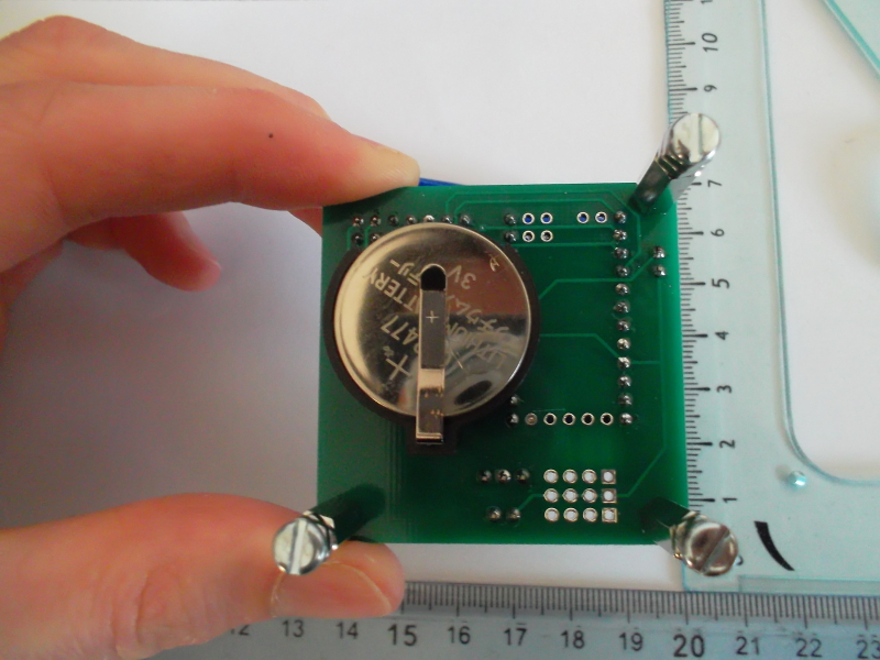
During the development process, power was measured to be to 300 uA at approximately 3.1 V in passive mode, with wake on interrupt enabled. In the door monitoring application, this is the default state. In practice, it allows a node to be powered using a 1000 mAh CR2477 coin cell battery for weeks.
I was also interested in the total power profile of sending one message over RF. At first, I measured it using a regulated power supply (ie. constant voltage set to 3.1V), so to have a feeling of the power:
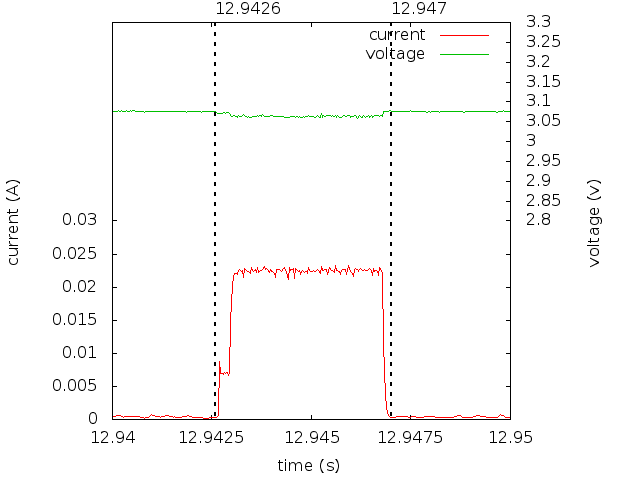
The current raises to around 25 mA for 5 ms. I knew it would be a problem for the coin cell. It actually was, and the battery voltage dropped too much to power the node electronics. I had to put a 330 uF in parallel to handle the peak. Here is the resulting profile, this time powered by a coin cell battery:
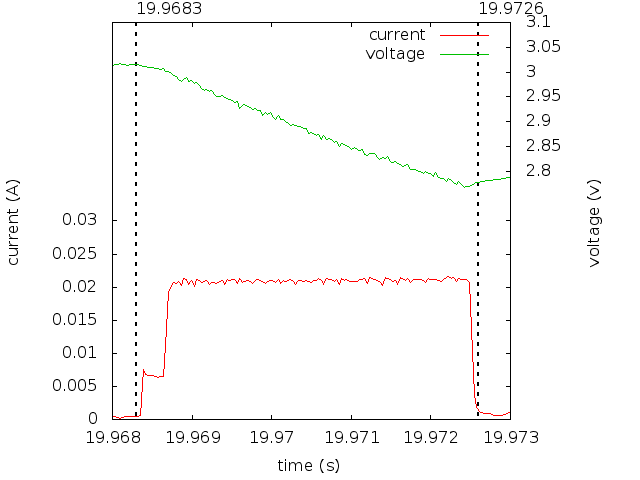
The voltage drops to 2.8 V during message transmission, which is fine as regard with the on board electronics. However, the node runtime should be careful not to send messages if the capacitor is not fully loaded. This is not an issue in the door monitoring application, but will have to be implemented for future applications.
Base station
The base station acts a bridge between the user and the BANO network. It collects node information and sends messages based on the network state and accordingly to the user configuration.
In its current implementation, the base station relies on a Beagle Bone Black board. There is no limitation on the board choice. For instance, a Raspberry PI could be used without software modification. The software can even run on a typical x86 platform, which is useful for development purposes.
It uses a NRF905 USB to serial bridge to communicate with the nodes. The bridge schematics are freely available here:
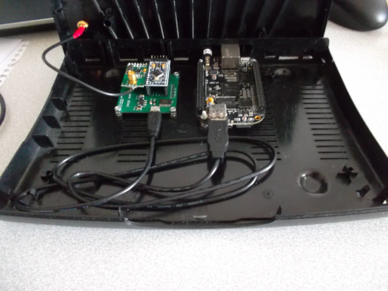
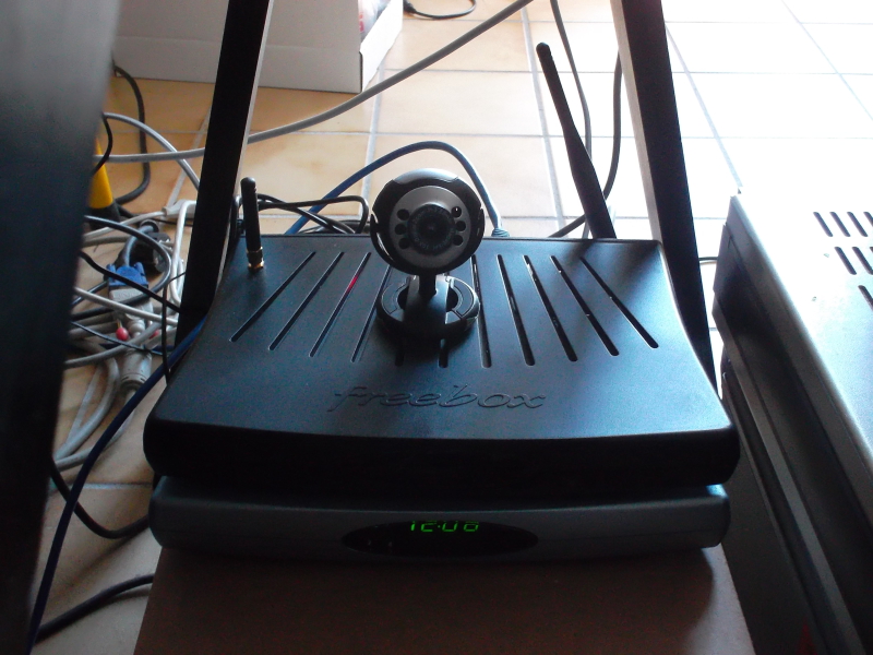
I packaged everything in a repurposed box and added a USB webcam. Here are some pictures of the end result:
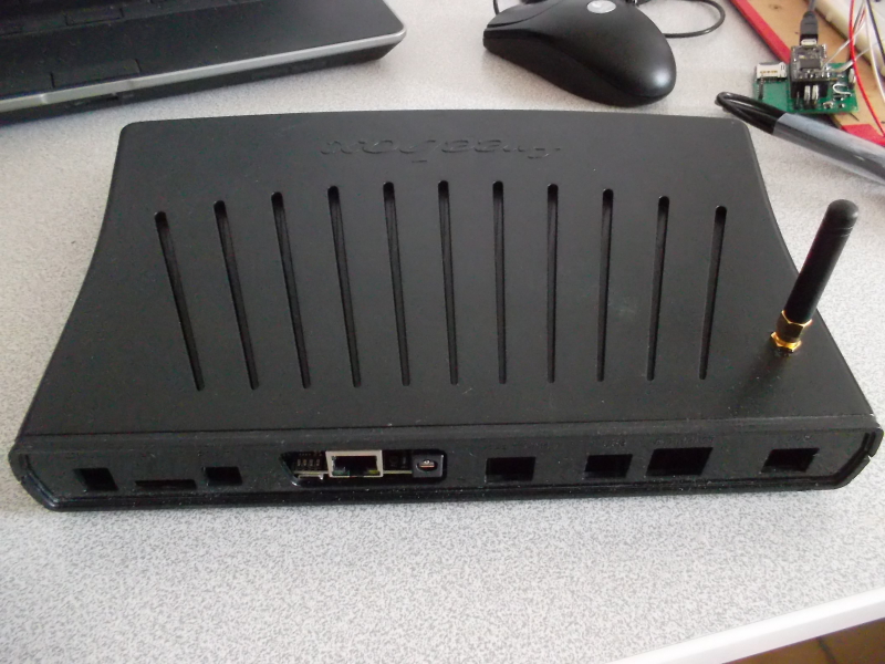
The base station is connected to the Internet and accessible over HTTP. Note that connectivity and HTTP are optionnal and can be configured by the user. The same applies regarding the RF transport layer.
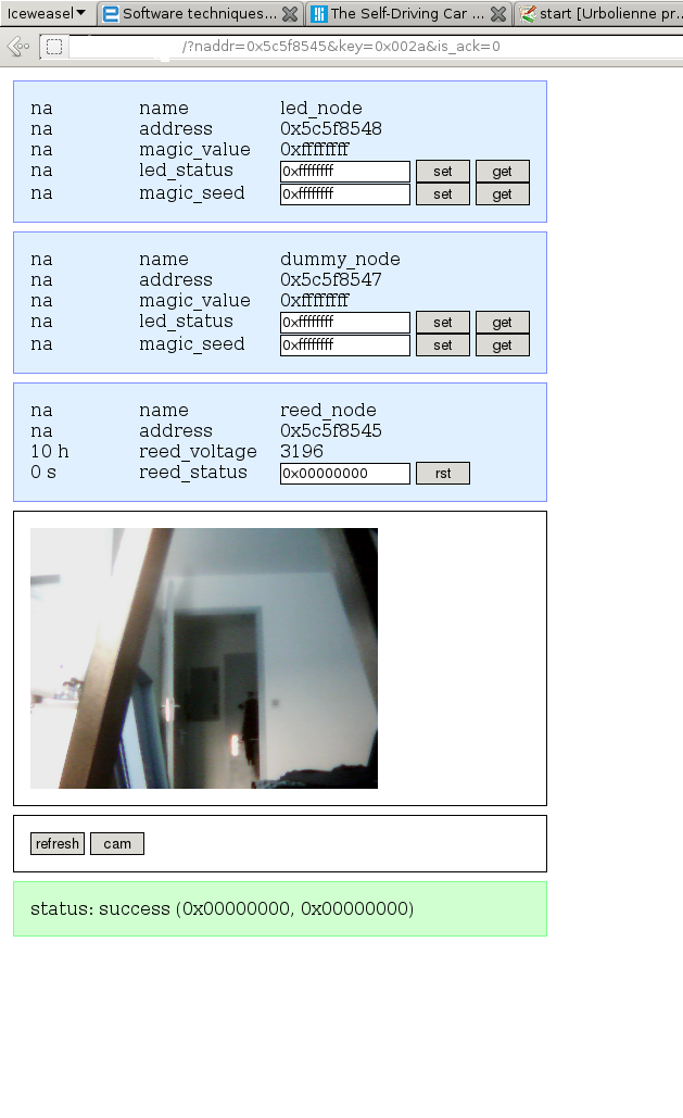
Since the base knows the BANO protocol, no programming work is needed to add support for a new node in the interface. It is only required to write a configuration file that describes specific key,value pairs. BANO calls these description files 'NODLes', short for 'node description language'. Once the base matches a nodl for a given node, it will automatically appear in the interface. Also, the interface provides controls so that the user can get or set a specific pair. Here is a screenshot of the web interface:
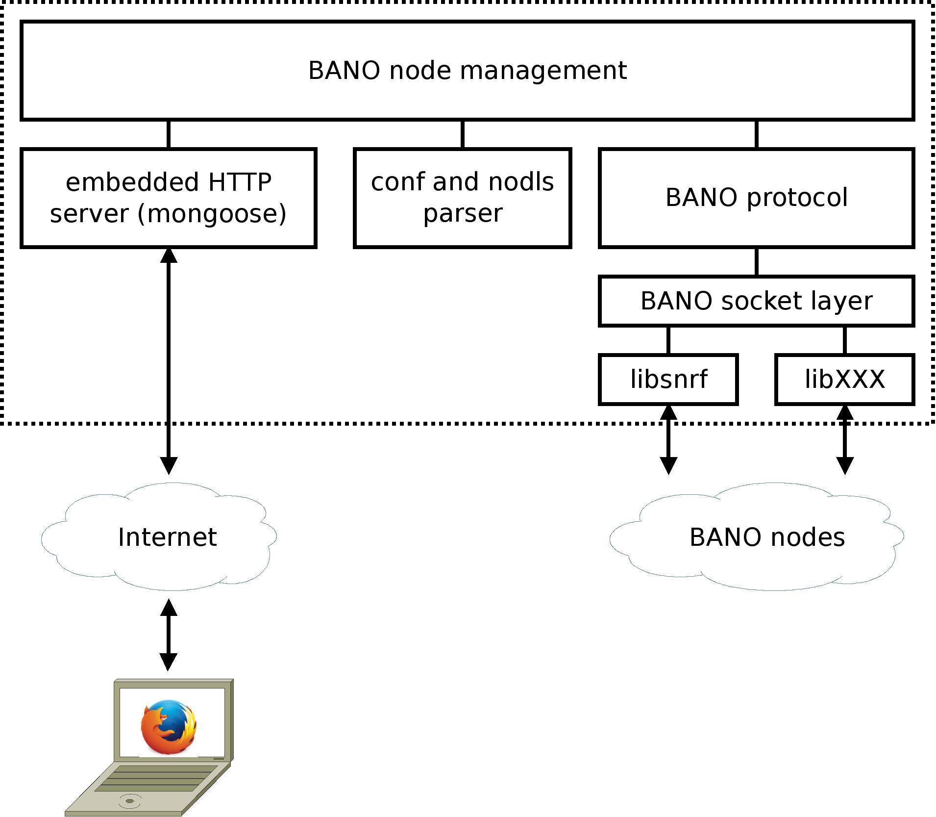
Finally, a diagram of the current base software implementation is available here:
Door monitor implementation
This section focuses on the implementation of the door monitor node itself. It has its own repository, available here:
https://github.com/texane/bano_reed
Node hardware platform
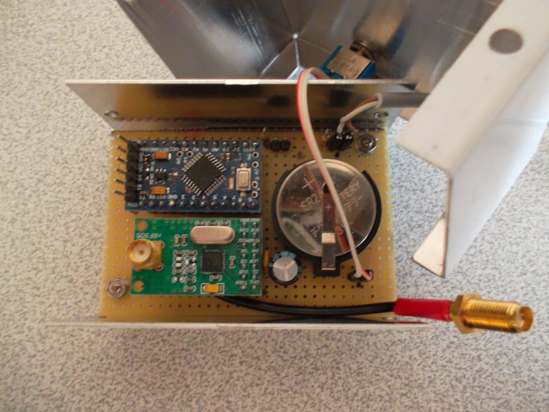
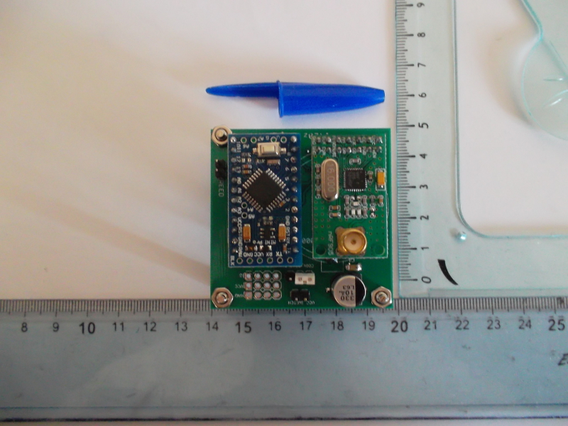
BANO does not enforce the use a specific hardware. For the door monitoring application, the node board consists of:
- an ARDUINO MINIPRO 3.3v for the logic,
- a NRF905 chipset for the RF stage,
- a reed switch.
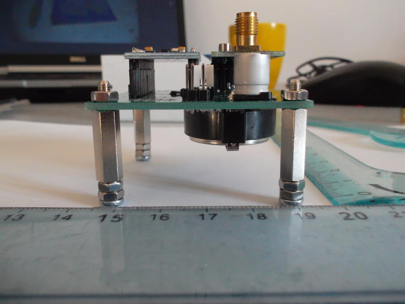
Here are some pictures of the board and setup used during the prototyping phase:
Once completed, I ordered from seeedstudio PCB fusion service:
http://www.seeedstudio.com/service/index.php?r=site/pcbService
It fits the 2 layers 50x50mm format, so total costs for 5 units are 18$, shipping included. Here are pictures of the final board:
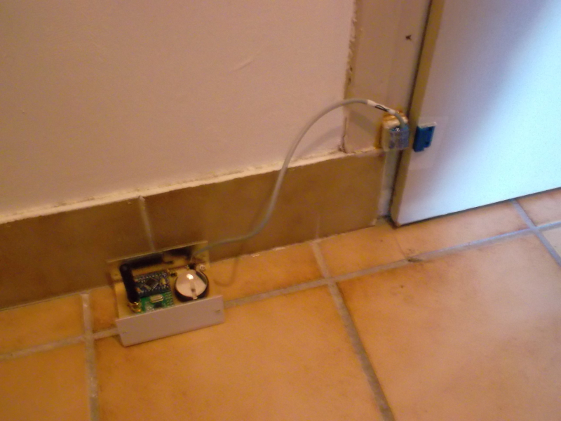
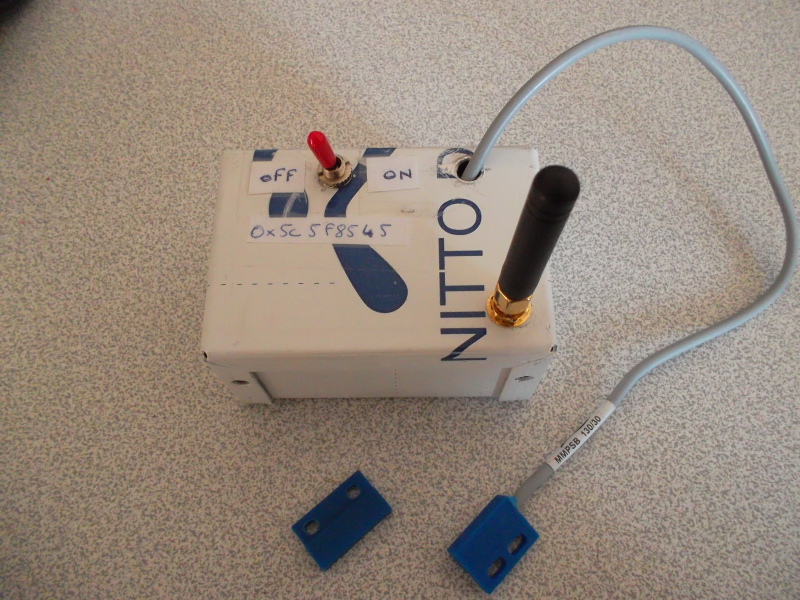
I put it inside an aluminium box, with a few indicators on it. The end result is here:
Software implementation
The full source code is available in one file:
https://github.com/texane/bano_reed/blob/master/src/node/main.c
BANO header file must first be included by the application:
#include "bano/src/node/bano_node.h"
The main routine initializes the node node runtime, so that it puts the node to sleep and wake up as the reed switch state changes:
/* initialize runtime info with default values */
bano_info_t info = bano_info_default;

/* wake on interrupt PCINT19 */
info.wake_mask = BANO_WAKE_PCINT;
info.pcint_mask = 1UL << 19UL;

/* enter the runtime main loop */
bano_init(&info);
It then sends the node voltage once to the base:
/* read the node voltage. its key value is 0x002b */
uint32_t vcc = get_vcc();
bano_send_set(0x002b, vcc);
The bano_pcint_handler routine is automatically called by the runtime whenever the reed switch state changes. It must be implemented by the node developer. In our case, it reads the switch state and send it to the base:
void bano_pcint_handler(void)
{
  /* send only if transition from low to high */
  /* status has key 0x002a */
  if (reed_is_high) bano_send_set(0x002a, 0x00000001);
}
The actual source code is a bit more complicated and includes debugging features. But the previous explaination summarizes quite well the node development simplicity, and shows how it hides low level details from the developer.
The Makefile relies on the BANO build system and is thus very short:
# from https://github.com/texane/bano_reed/blob/master/src/node/Makefile

BANO_C_FILES := main.c
BANO_BOARD := minipro_3v3
BANO_NODE_ADDR := 0x5c5f8545

include $(BANO_DIR)/build/node/top.mk
The corresponding NODL file is available in the base repository:
https://github.com/texane/bano/blob/master/src/base/nodl/00000001.nodl
Conclusion
I have been using BANO for some weeks now, and I am quite satisfied. It works well, and it is robust to communication errors. Needless to say it involved lot of debugging. Also, I continuously add features to the software without modifying the core design, which is a good sign.
There are a lot of details not covered in this article, but I think it is a good introduction to the framework feature. It is still a work in progress, and I willinclude features based on future developments, and eventual feedbacks.


- Comments
- Write a Comment Select to add a comment
Wow!
Congrats! i was just looking to purchase this an hour ago... http://www.wirelesstag.net/ so you can see you're in the price range. But i like yours even better 'cause it's OpenSource!!!
Have a great evening! :)

that is really good study
i am studying on patient monitoring based on zig bee and use Atmel microcontroller. could you reccomend something to do that.... thank you very much
I am sorry I can not help without more details. Plus, I do not know about the regulations involved in wireless devices when used for medical application.
To post reply to a comment, click on the 'reply' button attached to each comment. To post a new comment (not a reply to a comment) check out the 'Write a Comment' tab at the top of the comments.
Please login (on the right) if you already have an account on this platform.
Otherwise, please use this form to register (free) an join one of the largest online community for Electrical/Embedded/DSP/FPGA/ML engineers:


