


Ada 2012 for ARM M3/M4 Released for Download
Previous Ada Tutorials
Ada 2012 Comes to ARM Cortex M3/M4
It's Here!
Great news - AdaCore now has their initial ARM Ada port available on their download site. You can get it by going to http://libre.adacore.com/download/ and working your way to the page titled "Download GNAT GPL and SPARK GPL Editions". There, under "Select Configurations" you will see ARM ELF for Linux and for Windows. Those are the ones you want.
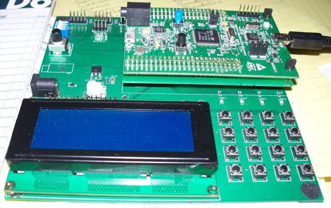
Porting the Ada runtime to a particular microcontroller, even the limited Ravenscar version, is a non-trivial task, and right now there are only a very few ARM Cortex parts supported. AdaCore is working on improving the porting process to make is as easy as possible. The board I'm using is the STM32F4 Discovery board:
Fifteen dollars for a 168MHz ARM board - not bad! Of course I wanted to get this board connected to my motherboard ASAP, so I designed an adaptor board to connect the one to the other. Here's the result (the adaptor board is the bottom board of the 2-board sandwich in the top right corner):
And it Speaks!
Once we confirm that the STM32F4 board is getting power and GND through the motherboard, the first goal, as always, is to get the LCD display running. Because Ada is a procedural language like C or C++, the earlier C code translates over in straightforward fashion. Here are the two files, starting with lcd.ads (the 'spec' file), which only exposes two LCD procedures (there are more in the package, but they are only for internal package use):
-- lcd.ads

with STM32F4;                     use STM32F4;

package LCD is

   pragma Elaborate_Body;

   procedure LCD_Init;
   procedure LCD_Put_String(X : Byte; Y : Byte; S : String);

end LCD;
and lcd.adb (the 'body' file):
-- ada.adb

with Ada.Real_Time;               use Ada.Real_Time;
with Registers;                   use Registers;
with Ada.Unchecked_Conversion;

package body LCD is

   type Bits is array (Natural range <>) of Boolean with Pack;

   subtype Bits_32 is Bits (0 .. 31);
   subtype Bits_8 is Bits (0 .. 7);

   function W_From_B32 is
     new Ada.Unchecked_Conversion (Source => Bits_32,
                                   Target => Word);

   function B32_From_W is
     new Ada.Unchecked_Conversion (Source => Word,
                                   Target => Bits_32);

   function B8_From_B is
     new Ada.Unchecked_Conversion (Source => Byte,
                                   Target => Bits_8);

   DISP_INIT   : Constant Byte := 16#30#;
   DISP_4BITS  : Constant Byte := 16#20#;
   DISP_ON     : Constant Byte := 16#0C#;
   DISP_OFF    : Constant Byte := 16#08#;
   DISP_CLR    : Constant Byte := 16#01#;
   DISP_EMS    : Constant Byte := 16#06#;
   DISP_CONFIG : Constant Byte := 16#28#;

   LCD_RS   : constant Word := 2**2;
   LCD_RW   : constant Word := 2**8;
   LCD_E    : constant Word := 2**9;
   LCD_BKLT : constant Word := 2**15;

   DD_RAM_ADDR  : constant Byte := 16#00#;
   DD_RAM_ADDR2 : constant Byte := 16#40#;
   DD_RAM_ADDR3 : constant Byte := 16#14#;
   DD_RAM_ADDR4 : constant Byte := 16#54#;

   LCD_BSRR_XOR : constant Word := 16#00F0_0000#; -- inverts LO-going D4..D7

-- spin wait on Ada.Realtime.Clock
   procedure Wait_Until(S : Time_Span) is
      T : Constant Time := Clock + S;
   begin
      while Clock < T loop
         null;
      end loop;
   end Wait_Until;

-- atomic set GPIO hi
   procedure LCD_Hi (Mask : Word) with Inline is
   begin
      GPIOE.BSRR := Mask;
   end LCD_Hi;

-- atomic set GPIO lo
   procedure LCD_Lo (Mask : Word) with Inline is
   begin
      GPIOE.BSRR := Shift_Left (Mask, 16);
   end LCD_Lo;

-- pulse LCD 'E' line hi
   procedure LCD_strobe is
   begin
      LCD_Hi(LCD_E);
      Wait_Until(Nanoseconds(500));
      LCD_Lo(LCD_E);
   end LCD_strobe;

-- write a Character to LCD in two 4-bit ops (not interrupt or multitask safe)
   procedure LCD_Write_4x2BitsX(C : Character) is
      gpio32 : Bits_32 with Size => 32;
      c8     : Bits_8 with Size => 8;
   begin
      Wait_Until(Microseconds(50));
      c8 := B8_From_B(Character'Pos(C));
      gpio32 := B32_From_W(GPIOE.ODR);
      gpio32(4..7) := c8(4..7);
      GPIOE.ODR := W_From_B32(gpio32);

      LCD_Strobe;

      gpio32(4..7) := c8(0..3);
      GPIOE.ODR := W_From_B32(gpio32);

      LCD_Strobe;

   end LCD_Write_4x2BitsX;

-- write a Character to LCD in two 4-bit ops (interrupt and multitask safe)
   procedure LCD_Write_4x2Bits(C : Character) is
      gpio32 : Bits_32 with Size => 32;
      gpiow  : Word;
      c8     : Bits_8 with Size => 8;
   begin
      Wait_Until(Microseconds(50));
      c8 := B8_From_B(Character'Pos(C));
      gpio32(0..31) := (others => False);
      gpio32(4..7) := c8(4..7);    -- Hi-going
      gpio32(20..23) := c8(4..7);  -- Lo-going
      gpiow := W_From_B32(gpio32);
      GPIOE.BSRR := gpiow xor LCD_BSRR_XOR;

      LCD_Strobe;

      gpio32(4..7) := c8(0..3);    -- Hi-going
      gpio32(20..23) := c8(0..3);  -- Lo-going
      gpiow := W_From_B32(gpio32);
      GPIOE.BSRR := gpiow xor LCD_BSRR_XOR; -- invert any Lo-going to 1s

      LCD_Strobe;

   end LCD_Write_4x2Bits;

-- write a Byte to LCD in two 4-bit ops (not interrupt or multitask safe)
   procedure LCD_Write_4x2BitsX(D : Byte) is
      gpio32 : Bits_32 with Size => 32;
      b8     : Bits_8 with Size => 8;
   begin
      Wait_Until(Microseconds(50));
      b8 := B8_From_B(D);
      gpio32 := B32_From_W(GPIOE.ODR);
      gpio32(4..7) := b8(4..7);
      GPIOE.ODR := W_From_B32(gpio32);

      LCD_Strobe;

      gpio32(4..7) := b8(0..3);
      GPIOE.ODR := W_From_B32(gpio32);

      LCD_Strobe;

   end LCD_Write_4x2BitsX;

-- write a Byte to LCD in two 4-bit ops (interrupt and multitask safe)
   procedure LCD_Write_4x2Bits(D : Byte) is
      gpio32 : Bits_32 with Size => 32;
      gpiow  : Word;
      b8     : Bits_8 with Size => 8;
   begin
      Wait_Until(Microseconds(50));
      b8 := B8_From_B(D);
      gpio32(0..31) := (others => False);
      gpio32(4..7) := b8(4..7);    -- Hi-going
      gpio32(20..23) := b8(4..7);  -- Lo-going
      gpiow := W_From_B32(gpio32);
      GPIOE.BSRR := gpiow xor LCD_BSRR_XOR;

      LCD_Strobe;

      gpio32(4..7) := b8(0..3);    -- Hi-going
      gpio32(20..23) := b8(0..3);  -- Lo-going
      gpiow := W_From_B32(gpio32);
      GPIOE.BSRR := gpiow xor LCD_BSRR_XOR; -- invert any Lo-going to 1s

      LCD_Strobe;

   end LCD_Write_4x2Bits;

-- write hi 4 bits of a Byte to LCD in one 4-bit op (not interrupt or multitask safe)
   procedure LCD_Write_4x1BitsX(D : Byte) is
      gpio32 : Bits_32 with Size => 32;
      b8     : Bits_8 with Size => 8;
   begin
      Wait_Until(Microseconds(50));
      b8 := B8_From_B(D);
      gpio32 := B32_From_W(GPIOE.ODR);
      gpio32(4..7) := b8(4..7);
      GPIOE.ODR := W_From_B32(gpio32);

      LCD_Strobe;
   end LCD_Write_4x1BitsX;

-- write hi 4 bits of a Byte to LCD in one 4-bit op (interrupt and multitask safe)
   procedure LCD_Write_4x1Bits(D : Byte) is
      gpio32 : Bits_32 with Size => 32;
      gpiow  : Word;
      b8     : Bits_8 with Size => 8;
   begin
      b8 := B8_From_B(D);
      gpio32(0..31) := (others => False);
      gpio32(4..7) := b8(4..7);    -- Hi-going
      gpio32(20..23) := b8(4..7);  -- Lo-going
      gpiow := W_From_B32(gpio32);
      GPIOE.BSRR := gpiow xor LCD_BSRR_XOR; -- invert any Lo-going to 1s

      LCD_Strobe;
   end LCD_Write_4x1Bits;

-- write a byte to LCD command register
   procedure LCD_Cmd(Cmd : Byte) is
   begin
      LCD_Lo(LCD_RS);
      LCD_Write_4x2Bits(Cmd);
   end LCD_Cmd;

-- software init LCD module
   procedure LCD_Init is
   begin
      LCD_Lo(LCD_E + LCD_RW + LCD_RS);

      LCD_Hi(LCD_BKLT);

      Wait_Until(Milliseconds(20));
      LCD_Write_4x1Bits(DISP_INIT);
      Wait_Until(Milliseconds(5));
      LCD_Write_4x1Bits(DISP_INIT);
      Wait_Until(Milliseconds(1));
      LCD_Write_4x1Bits(DISP_INIT);
      Wait_Until(Milliseconds(1));
      LCD_Write_4x1Bits(DISP_4BITS);
      Wait_Until(Milliseconds(1));

      LCD_Cmd(DISP_CONFIG);
      LCD_Cmd(DISP_OFF);
      LCD_Cmd(DISP_CLR);
      Wait_Until(Milliseconds(2));  -- undocumented but required!
      LCD_Cmd(DISP_EMS);
      LCD_Cmd(DISP_ON);
   end LCD_Init;

-- write Character to LCD data register
   procedure LCD_Put_Char(C : Character) is
   begin
      LCD_Hi(LCD_RS);
      LCD_Write_4x2Bits(C);
   end LCD_Put_Char;

-- write String to LCD at specified XY location
   procedure LCD_Put_String(X : Byte; Y : Byte; S : String) is
      Base : Byte;
   begin
      case Y is
         when 0 => Base := DD_RAM_ADDR;
         when 1 => Base := DD_RAM_ADDR2;
         when 2 => Base := DD_RAM_ADDR3;
         when 3 => Base := DD_RAM_ADDR4;
         when others => Base := DD_RAM_ADDR;
      end case;

      LCD_Cmd(Base + X + 16#80#);  -- addr command

      for i in S'Range loop
         LCD_Put_Char(S(i));
      end loop;

   end LCD_Put_String;

end LCD;
But Wait, There's More!
One of the things I really like about Ada is how much realtime and tasking stuff is built into the language. Among the things to notice in this code is that nowhere are any timers configured. This is something provided by the Ada runtime. In particular, Ada.Realtime provides a clock (called 'Clock') that is guaranteed to have a resolution no worse than 100 microseconds, and to have a period of no less than 50 years. In this port, the resolution is the system clock resolution, or 1/168 Mhz (that is, about 6ns).
For short delays we can spin-wait on this Clock, employing user-written procedures such as Wait_Until(). This procedure takes a time span which it adds to the current time to calculate a future time. Then it spins (runs in an empty loop) until Clock reaches that future time.
For longer delays, Ada provides 'delay' and 'delay until'. The ARM Ravenscar runtime only allows 'delay until', which is one of the (fairly reasonable) limitations of the Ravenscar profile. What makes these delays different from the Wait_Until type of procedures is (1) these delays are built into the language, and (2) these delays allow for a task switch, so they're not just burning up cycles in a loop. That is, a delay or delay until can allow the executing task to yield to another ready task. Executing the code to check for any expiring delays takes time, so the resolution of the delay time intervals is only guaranteed by the Ada language to be 1 millisecond (and that is the resolution in this ARM runtime).
The LCD_Write...X procedures (3 of them) do the same thing as the non-X versions, but they do a RMW (read-modify-write) operation on the GPIO output register, making them potentially unsafe if other tasks or interrupts can also access the output register. I left them in because they are easier to understand than the non-X versions, and because they show the universal approach, one that works even with hardware that doesn't have special GPIO set/reset registers, but if this approach is used you'll have to take the necessary steps to prevent corruption of the output register, or to guarantee that such corruption cannot happen.
The non-X versions of the LCD write procedures write to the BSRR register, making the operation atomic. To do this, the '1' bits are transferred to the corresponding 'set to 1' bits of the BSRR, while the '0' bits are transferred to the corresponding 'set to 0' bits of the BSRR. The '0' bits then need to be inverted to 1s, which is the purpose of the xor operation. So the single write to the BSRR register sets all the '1' bits and clears all the '0' bits, atomically. No fuss, no muss!
For me, one of the most interesting things in the LCD code is the use of Boolean arrays and array slices to copy the 4-bit LCD data from the 8 bit source word into the 32 bit GPIO output register. The array slice operations hide all the masking and shifting and make the operation being performed much more clear, IMO. To me this is a good example of working in the problem space (I want to put source bits 0..3 into destination bits 4..7) rather than in the solution space (masking the source bits, shifting them into position, clearing the destination bits, and oring in the shifted source bits).
Notice also that since array slicing only works for the same array types, the parent type is an array declared with an indefinite range (using <> in the declaration). Then the 32 bit and 8 bit Boolean arrays are declared as subtypes of this type, which makes them the same type for the purposes of the array slicing.
Finally notice the Unchecked Conversions that have been declared to convert back and forth between modular (unsigned) integers and arrays of Boolean. In Ada you really need to be explicit to do things like this, but it's not an uncommon requirement for low level programming.
The rest of the program is essentially the same LED circling program we had last time, but with the addition of the LCD_Init procedure as part of the initialization, and the addition of writing out the active LED color on each color change.
All the source code for this example can be found in this zipped folder. In addition, I've listed much of the code below just because it is interesting to see how Ada does things. Most of this code should be pretty easy to read for a C or C++ programmer.
Here is driver.adb, which contains the main program task and which now uses this new LCD code:
-- driver.adb

with LEDs;          use LEDs;
with LCD;           use LCD;
with Button;        use Button;
with Ada.Real_Time; use Ada.Real_Time;
with STM32F4;       use STM32F4;

package body Driver is

   type Index is mod 4;

   Pattern : constant array (Index) of User_LED := (Orange, Red, Blue, Green);
   --  The LEDs are not physically laid out "consecutively" in such a way that
   --  we can simply go in enumeral order to get circular rotation. Thus we
   --  define this mapping, using a consecutive index to get the physical LED
   --  blinking order desired.

   task body Controller is
      Period     : constant Time_Span := Milliseconds (500);  -- arbitrary
      Next_Start : Time := Clock;
      Next_LED   : Index := 0;
      subtype C_String is String(1..6);
      S_Blanks   : constant C_String := "      ";
      S_Orange   : constant C_String := "Orange";
      S_Red      : constant C_String := "Red   ";
      S_Blue     : constant C_String := "Blue  ";
      S_Green    : constant C_String := "Green ";
      LED_Names  : constant array(Index) of C_String
                   := (S_Orange, S_Red, S_Blue, S_Green);
      LED_X      : constant array(Index) of Byte := (14, 8, 0, 7);
      LED_Y      : constant array(Index) of Byte := (1, 2, 1, 0);

   begin
      loop
         LCD_Put_String(LED_X(Next_LED), LED_Y(Next_LED), S_Blanks);
         Off (Pattern (Next_LED));

         if Button.Current_Direction = Counterclockwise then
            Next_LED := Next_LED - 1;
         else
            Next_LED := Next_LED + 1;
         end if;

         LCD_Put_String(LED_X(Next_LED), LED_Y(Next_LED), LED_Names(Next_LED));
         On (Pattern (Next_LED));

         Next_Start := Next_Start + Period;
         delay until Next_Start;
      end loop;
   end Controller;

end Driver;
You can see that besides setting a new LED pattern each time through the loop, the code also puts the LED color name onto the screen in a corresponding location. Also remember from the last Ada tutorial that since 'Next_LED' is a modular type, it automatically wraps, so there is no need to handle wrapping in the code. Nice.
--driver.ads

--  This file provides the declaration for the task controlling the LEDs on
--  the STM32F4 Discovery board.

with System;

package Driver is

   task Controller is
      pragma Storage_Size (4 * 1024);
      pragma Priority (System.Default_Priority);
   end Controller;

end Driver;
The LED files:
-- leds.ads

--  This file provides declarations for the user LEDs on the STM32F4 Discovery
--  board from ST Microelectronics.

with STM32F4;  use STM32F4;

package LEDs is
   pragma Elaborate_Body;

   type User_LED is (Green, Orange, Red, Blue);

   for User_LED use
     (Green  => 16#1000#,
      Orange => 16#2000#,
      Red    => 16#4000#,
      Blue   => 16#8000#);

   --  As a result of the representation clause, avoid iterating directly over
   --  the type since that will require an implicit lookup in the generated
   --  code of the loop.  Such usage seems unlikely so this direct
   --  representation is reasonable, and efficient.

   for User_LED'Size use Word'Size;
   --  we convert the LED values to Word values in order to write them to
   --  the register, so the size must be the same

   LED3 : User_LED renames Orange;
   LED4 : User_LED renames Green;
   LED5 : User_LED renames Red;
   LED6 : User_LED renames Blue;

   procedure On  (This : User_LED) with Inline;
   procedure Off (This : User_LED) with Inline;

   procedure All_Off with Inline;
   procedure All_On  with Inline;

end LEDs;
Since this file already had the LED GPIO configuration, I added the LCD configuration here as well. Notice here that arrays and slices are used to configure both single bit and 2 bit fields of the GPIO registers. Tell me that's not sweet!
-- leds.adb

with Ada.Unchecked_Conversion;

with Registers;     use Registers;
with STM32F4.GPIO;  use STM32F4.GPIO;
with LCD;

package body LEDs is


   function As_Word is new Ada.Unchecked_Conversion
     (Source => User_LED, Target => Word);


   procedure On (This : User_LED) is
   begin
      GPIOD.BSRR := As_Word (This);
   end On;


   procedure Off (This : User_LED) is
   begin
      GPIOD.BSRR := Shift_Left (As_Word (This), 16);
   end Off;


   All_LEDs_On  : constant Word := Green'Enum_Rep or Red'Enum_Rep or
                                   Blue'Enum_Rep  or Orange'Enum_Rep;

   pragma Compile_Time_Error
     (All_LEDs_On /= 16#F000#,
      "Invalid representation for All_LEDs_On");

   All_LEDs_Off : constant Word := Shift_Left (All_LEDs_On, 16);


   procedure All_Off is
   begin
      GPIOD.BSRR := All_LEDs_Off;
   end All_Off;


   procedure All_On is
   begin
      GPIOD.BSRR := All_LEDs_On;
   end All_On;


   procedure Initialize is
      RCC_AHB1ENR_GPIOD : constant Word := 16#08#;
      RCC_AHB1ENR_GPIOE : constant Word := 16#10#;
   begin
      --  Enable clock for GPIO-D and GPIO-E
      RCC.AHB1ENR := RCC.AHB1ENR or RCC_AHB1ENR_GPIOD or RCC_AHB1ENR_GPIOE;

      --  Configure PD12-15
      GPIOD.MODER   (12 .. 15) := (others => Mode_OUT);
      GPIOD.OTYPER  (12 .. 15) := (others => Type_PP);
      GPIOD.OSPEEDR (12 .. 15) := (others => Speed_100MHz);
      GPIOD.PUPDR   (12 .. 15) := (others => No_Pull);

      --  Configure PE4-9 (4-7 LCD data, 8 LCD RW, 9 LCD E
      GPIOE.MODER   (4 .. 9) := (others => Mode_OUT);
      GPIOE.OTYPER  (4 .. 9) := (others => Type_PP);
      GPIOE.OSPEEDR (4 .. 9) := (others => Speed_100MHz);
      GPIOE.PUPDR   (4 .. 9) := (others => No_Pull);
      --  Configure PE2
      GPIOE.MODER   (2) := Mode_OUT;
      GPIOE.OTYPER  (2) := Type_PP;
      GPIOE.OSPEEDR (2) := Speed_100MHz;
      GPIOE.PUPDR   (2) := No_Pull;
      --  Configure PE15
      GPIOE.MODER   (15) := Mode_OUT;
      GPIOE.OTYPER  (15) := Type_PP;
      GPIOE.OSPEEDR (15) := Speed_100MHz;
      GPIOE.PUPDR   (15) := No_Pull;
   end Initialize;


begin
   Initialize;
   LCD.LCD_Init;
end LEDs;
Declaring the GPIO registers and some other configuration registers
-- registers.ads

with System;
with STM32F4;                     use STM32F4;
with STM32F4.GPIO;                use STM32F4.GPIO;
with STM32F4.Reset_Clock_Control; use STM32F4.Reset_Clock_Control;
with STM32F4.SYSCONFIG_Control;   use STM32F4.SYSCONFIG_Control;

package Registers is

   pragma Warnings (Off, "*may call Last_Chance_Handler");
   pragma Warnings (Off, "*may be incompatible with alignment of object");

   RCC : RCC_Register with
     Volatile,
     Address => System'To_Address (RCC_Base);

   GPIOA : GPIO_Register with
     Volatile,
     Address => System'To_Address (GPIOA_Base);
   pragma Import (Ada, GPIOA);

   GPIOD : GPIO_Register with
     Volatile,
     Address => System'To_Address (GPIOD_Base);
   pragma Import (Ada, GPIOD);

   GPIOE : GPIO_Register with
     Volatile,
     Address => System'To_Address (GPIOE_Base);
   pragma Import (Ada, GPIOE);

   EXTI : EXTI_Register with
     Volatile,
     Address => System'To_Address (EXTI_Base);
   pragma Import (Ada, EXTI);

   SYSCFG : SYSCFG_Register with
     Volatile,
     Address => System'To_Address (SYSCFG_Base);
   pragma Import (Ada, SYSCFG);

   pragma Warnings (On, "*may call Last_Chance_Handler");
   pragma Warnings (On, "*may be incompatible with alignment of object");

end Registers;
Declaring some data types and some register memory addresses
-- stm32f4.ads

pragma Restrictions (No_Elaboration_Code);

with Interfaces;

package STM32F4 is

   type Word      is new Interfaces.Unsigned_32;  -- for shift/rotate
   type Half_Word is new Interfaces.Unsigned_16;  -- for shift/rotate
   type Byte      is new Interfaces.Unsigned_8;   -- for shift/rotate

   type Bits_1  is mod 2**1 with Size => 1;
   type Bits_2  is mod 2**2 with Size => 2;
   type Bits_4  is mod 2**4 with Size => 4;

   type Bits_32x1 is array (0 .. 31) of Bits_1 with Pack, Size => 32;
   type Bits_16x2 is array (0 .. 15) of Bits_2 with Pack, Size => 32;
   type Bits_8x4  is array (0 ..  7) of Bits_4 with Pack, Size => 32;

   type Bits_8x1 is array (0 .. 7) of Bits_1 with Pack, Size => 8;

   --  Define address bases for the various system components

   Peripheral_Base : constant := 16#4000_0000#;

   APB1_Peripheral_Base : constant := Peripheral_Base;
   APB2_Peripheral_Base : constant := Peripheral_Base + 16#0001_0000#;
   AHB1_Peripheral_Base : constant := Peripheral_Base + 16#0002_0000#;
   AHB2_Peripheral_Base : constant := Peripheral_Base + 16#1000_0000#;

   GPIOA_Base           : constant := AHB1_Peripheral_Base + 16#0000#;
   GPIOB_Base           : constant := AHB1_Peripheral_Base + 16#0400#;
   GPIOC_Base           : constant := AHB1_Peripheral_Base + 16#0800#;
   GPIOD_Base           : constant := AHB1_Peripheral_Base + 16#0C00#;
   GPIOE_Base           : constant := AHB1_Peripheral_Base + 16#1000#;

   FLASH_Base           : constant := AHB1_Peripheral_Base + 16#3C00#;
   RCC_Base             : constant := AHB1_Peripheral_Base + 16#3800#;

   PWR_Base             : constant := APB1_Peripheral_Base + 16#7000#;

   USART1_Base          : constant := APB2_Peripheral_Base + 16#1000#;
   SYSCFG_Base          : constant := APB2_Peripheral_Base + 16#3800#;
   EXTI_Base            : constant := APB2_Peripheral_Base + 16#3C00#;

end STM32F4;
Declaring GPIO configuration values
-- stm32f4-gpio.ads

pragma Restrictions (No_Elaboration_Code);

package STM32F4.GPIO is

   --  MODER constants
   Mode_IN      : constant Bits_2 := 0;
   Mode_OUT     : constant Bits_2 := 1;
   Mode_AF      : constant Bits_2 := 2;
   Mode_AN      : constant Bits_2 := 3;

   --  OTYPER constants
   Type_PP      : constant Bits_1 := 0; -- Push/pull
   Type_OD      : constant Bits_1 := 1; -- Open drain

   --  OSPEEDR constants
   Speed_2MHz   : constant Bits_2 := 0; -- Low speed
   Speed_25MHz  : constant Bits_2 := 1; -- Medium speed
   Speed_50MHz  : constant Bits_2 := 2; -- Fast speed
   Speed_100MHz : constant Bits_2 := 3; -- High speed on 30pF, 80MHz on 15

   --  PUPDR constants
   No_Pull      : constant Bits_2 := 0;
   Pull_Up      : constant Bits_2 := 1;
   Pull_Down    : constant Bits_2 := 2;

   --  AFL constants
   AF_USART1    : constant Bits_4 := 7;

   --  Reset constants
   GPIOA_Reset       : constant Word := 16#A800_0000#;
   GPIOB_Reset       : constant Word := 16#0000_0280#;
   GPIO_Others_Reset : constant Word := 16#0000_0000#;


   type GPIO_Register is record
      MODER   : Bits_16x2;  --  mode register
      OTYPER  : Bits_32x1;  --  output type register
      OSPEEDR : Bits_16x2;  --  output speed register
      PUPDR   : Bits_16x2;  --  pull-up/pull-down register
      IDR     : Word;       --  input data register
      ODR     : Word;       --  output data register
      BSRR    : Word;       --  bit set/reset register
      LCKR    : Word;       --  configuration lock register
      AFRL    : Bits_8x4;   --  alternate function low register
      AFRH    : Bits_8x4;   --  alternate function high register
   end record;

   for GPIO_Register use record
      MODER   at 0  range 0 .. 31;
      OTYPER  at 4  range 0 .. 31;
      OSPEEDR at 8  range 0 .. 31;
      PUPDR   at 12 range 0 .. 31;
      IDR     at 16 range 0 .. 31;
      ODR     at 20 range 0 .. 31;
      BSRR    at 24 range 0 .. 31;
      LCKR    at 28 range 0 .. 31;
      AFRL    at 32 range 0 .. 31;
      AFRH    at 36 range 0 .. 31;
   end record;

end STM32F4.GPIO;
The main program file. Notice that it just spins in a forever loop. All the action happens in the drivers package, in the task called 'Controller', so this file 'withs' the driver package but does not reference it.
-- demo.adb

with Driver;               pragma Unreferenced (Driver);
--  The Driver package contains the task that actually controls the app so
--  although it is not referenced directly in the main procedure, we need it
--  in the closure of the context clauses so that it will be included in the
--  executable.

with Last_Chance_Handler;  pragma Unreferenced (Last_Chance_Handler);
--  The "last chance handler" is the user-defined routine that is called when
--  an exception is propagated. We need it in the executable, therefore it
--  must be somewhere in the closure of the context clauses.

with System;

procedure Demo is
   pragma Priority (System.Priority'First);
begin
   loop
      null;
   end loop;
end Demo;
The Video
Because the world can never have too many blinking LED videos! This is just raw video because my video editing software is on the fritz. I'll really have to try a different camera, too, because this one makes the nice crisp LCD display look like its been submerged in vaseline.
Next time I'm hoping to drive a multiplexed 7-segment display (I just sent off the board files today), and to demonstrate some of Ada's runtime error catching ability.


- Comments
- Write a Comment Select to add a comment
Jerry

I need to reliably communicate with things like:
1. GPS receiver (I2C, UART).
2. microSD card (SPI) or get direct access to the STM32F4s SDIO bus.
3. Get direct access to the RTC for syncing it with the GPS time pulse.
4. Get direct access to the on-board 10/100 Ethernet MAC or via SPI to off-board controllers.
My email address is roy dot emmerich at infinite fingers dot com
My first language back in the 70's was machine code loaded into core memory from a hex keypad. So I was very happy when I found Ada with its support of so many real time "on the metal" feathers. Bit mapped records, memory overlays, interrupt handlers, real time clocks, timer callbacks, threads (tasks), thread safe data modules (protected objects), its got them all. It also supports programming in the large with things like abstract data types (private and limited types), packages, families of packages, and of course all of the OOP stuff as well.
The thing I like most about Ada is the way I feel as I create layer after layer of code, ... it makes me feel safe! It allows me to decompose a system into a network of smaller modules each one with a specification (interface) and a nice safe body (implementation). I know all those modules are going to fit together and play nice because of the language. Ada doesnt give me that tinny feeling I get with other languages, it feels sturdier, more solid.
Oh well enough rant. Its nice to see this kind of stuff, and youre right, I never get tired of the blinking lights!
I agree that one of the big appeals of Ada is all that great realtime, system and concurrency support. I hope people will look past the 30-year old snark (some earned, most not) and look at the modern language with an open mind. They may find themselves surprised to discover a gem.
I am in the process of developing a modular, open source data logging platform and am playing with a few high level alternatives to C, namely:
1. Espruino (JavaScript)
2. Micro Python
3. eLua
So far Espruino is the best compromise because:
a. Getting code onto the chip is easy (copy/paste - purely interpreted - no compilation required) compared to setting up a toolchain in C
b. There are tons of libraries/examples at https://www.npmjs.org
c. The basics are working well on the STM32F4 micro.
d. There are tons of people who develop in JavaScript who would be willing to join my open source community around my products.
Worries:
a. Maturity. So far there is no track record for Espruino or JavaScript on microcontrollers
b. Code size. What happens when projects become large? Will it all fit on?
c. Real-time. I don't think it will operate deterministically, especially under heavy load, as it is interpreted.
Then yesterday I stumbled upon Ada as a real (time) alternative. I spent quite a number of hours going through various content on the web and wondered why I hadn't come across this option before! Your two posts on this site helped to make it more tangible for me (as well as William Wong from http://electronicdesign.com). A lot of what I found on Ada focuses heavily on how robust it is but fails to make it accessible to the tinkerer.
Although I am very convinced by what I've read, for Ada to be a viable alternative for my project, I would need to get up and running quickly. Things that would accelerate progress, over and above the (super) AdaCore University, is to get access to libraries and examples for doing the basics in Ada. Stuff like:
1. Communication: SPI, I2C, Serial, Ethernet, one-wire
2. Libraries: MODBUS RTU/Eth at the very least
3. Direct access to chip functionality: STM32F4 RTC, Precision Time Protocol capabilities on chip, etc. I read that binding in C code is fairly easy? That would allow me to directly call the STM32 C drivers provided by STM?
4. Someone hosts an open forum to encourage the exchange of ideas, providing an alternative to the normally clandestine military/large corporate approach to code development. If Ada is going to grow then it needs to open up to your average Joe like me :)
I'd love to hear your feedback.
In no particular order I know of these online resources (which may also link to other resources)
http://en.wikibooks.org/wiki/Ada_Programming
http://en.wikibooks.org/wiki/Ada_Programming/Tutorials
http://www.sigada.org/education/pages/Ada-Distilled-07-27-2003-Color-Version.pdf
Even Ada 95 resources are very useful, since they cover 90% or more of the actual Ada you'll be writing.
John Barnes has Ada books on Ada 2005 and Ada 2012.
Burns and Wellings have put out great books on Ada concurrency
This is also a good book on realtime and concurrency:
http://www.amazon.com/Building-Parallel-Embedded-Real-Time-Applications/dp/0521197163
I can't say anything about Espruino or the other languages you're looking at, but I can say a few things about Ada and the STM32F4 family.
I know that AdaCore is working on comms libraries for the ARM Cortex M parts, but I don't know anything about the projected availability. I can tell you that writing the low-level stuff in Ada can be very similar to writing in C, almost on a line-for-line basis. It may not be the best Ada style, but you can refactor later if you choose. In any case, you will have no problem accessing the chip hardware in Ada.
It is also true that you can link to C code in Ada with either thin or thick wrappers. A thin wrapper just converts each C function to an equivalent Ada subprogram, while a thick wrapper adds one or more higher-level layers on top of the basic subprograms.
I strongly agree that Ada needs to open up to the average Joe, for the benefit of both. comp.lang.ada would be a good place to start looking for like-minded souls.
In the meantime, download the Ada ARM package, buy the STM32F407 discovery board, and get your feet wet. Best of luck.
Mike
I already have the hardware to get up and running but without the communication libraries it isn't much use. I'm in prototyping stage and am currently fighting with hardware, just trying to set everything up and get it working semi-reliably.
Thanks for the heads up on comp.lang.ada. I'm busy writing a similar post there to see whether any other ideas pop out.
Breathing space is rather limited at the moment but I certainly will download Ada and start playing around. When those comms libraries hit the servers it will be a formidable competitor and since what I am doing is a long term project, it seems Ada is something I could fall in love with :)
In comparison to helping set up the C toolchain for chibios this was an absolute breeze!
Now it's time to really start learning. First stop is the Ada University. Do you have any other tips on how to get going quickly?
favourite justification seemed to be at the internet the easiest factor to be
aware of. I say to you, I certainly get annoyed at the same time
as other folks consider concerns that they just dont realize about.
You managed to hit the nail upon the highest as well as
defined out the entire thing without having side effect , people could
take a signal. Will probably be again to get more. Thanks
Definitely imagine that which you said. Your
favourite justification seemed to be at the internet the easiest factor to be
aware of. I say to you, I certainly get annoyed at the same time
as other folks consider concerns that they just dont realize about.
You managed to hit the nail upon the highest as well as
defined out the entire thing without having side effect , people could
take a signal. Will probably be again to get more. Thanks
To post reply to a comment, click on the 'reply' button attached to each comment. To post a new comment (not a reply to a comment) check out the 'Write a Comment' tab at the top of the comments.
Please login (on the right) if you already have an account on this platform.
Otherwise, please use this form to register (free) an join one of the largest online community for Electrical/Embedded/DSP/FPGA/ML engineers:


