


Best Firmware Architecture Attributes
Architecture of a firmware (FW) in a way defines the life-cycle of your product. Often companies start with a simple-version of a product as a response to the time-to-market caveat of the business, make some cash out of the product with a simple feature set. It takes only less than 2-3 years to reach a point where the company needs to develop multiple products derived from the same code base and multiple teams need to develop various other new features simultaneously. This could be efficiently achieved only if you started with a good FW architecture. If not, at some point, your company will need a substantial amount of effort to either re-factor your code or even you need to re-architect and re-write the code from scratch.
What are then the best architecture attributes?
Modularity
Modularity is important. Instead of a firmware application that has several thousands of lines of code with no boundaries in terms of responsibilities, one should have a set of modules that are responsible for executing different parts of the application. That way, similar products can be derived from the same code base with addition of new modules or modification of existing modules that would do the differentiation. In any case, most of the modules will be reused to develop a new product.
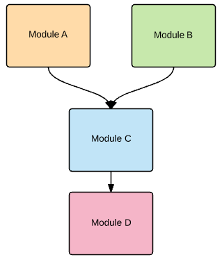
Figure 1 - An example to a modular firmware consisting of different modulesIn
Low coupling
What is coupling or dependency exactly then?
Coupling or dependency for a module is defined as being dependent on another module (meaning module A is reading from or writing to a variable in module C in the example above) to compile or successfully run during run-time. Therefore, there's a compile-time and run-time dependency. What we are talking about here is compile-time dependency. In this case, the application code is not even compiled without existence of the modules that the other modules depend on.
Figure -2 An illustration of dependency
In Figure-2, Module B depends on Module A to compile because the variable "color" used in Module B is actually defined in Module A.
Imagine you had a firmware consisted of 6 modules and there were compile-time dependencies from almost each module to the others. That would be the worst case you would be in because even if you need to change a single thing in one module, you may end up making changes in another five modules. For instance, a change in Module C may trigger a change in Module A, B, D and E in the example below.
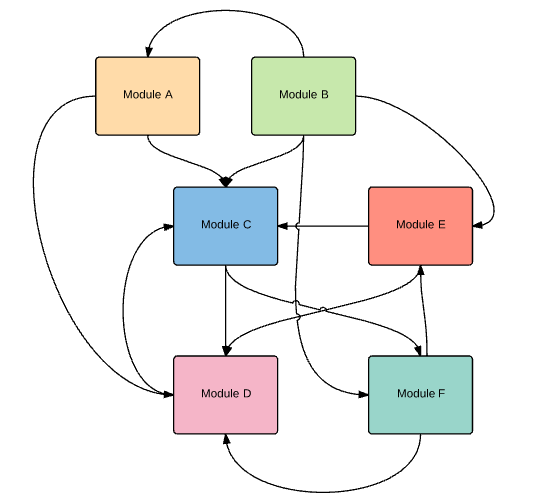
Figure-3 "Spaghetti Diagram" where there are dependencies all over the place
If there low coupling concern is not addressed in a firmware architecture from the beginning, dependencies among the modules could turn into the one illustrated in Figure-3. This kind of dependency diagram could be called "spaghetti diagram". Fixing issues in such dependency could be very cumbersome and module reuse per product with minimal changes could not be possible. That means redundant development cost to the company.
Another issue could be "circular dependency". Figure-3 illustrates the circular dependency which is another bad practice. If one wants to use a module in another project, he/she must also bring the other module that is not needed along with the one needed. Therefore, it costs extra Flash memory. Circular dependencies should not be allowed between modules.
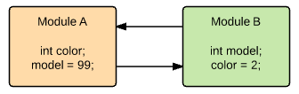
Figure - 4 Circular dependency
Therefore, it is good to follow the best practices
- Dependencies among modules should be as minimum as possible to maintain the amount of change at a minimum when a small change is needed in a feature.
- Each module should have single responsibility.
- From a design perspective, low coupling can be maintained by defining dependency rules.
- Quality should be measured by design and code review.
- There should not be circular dependencies between modules.
You could use Doxygen in your build system to see the dependencies in your FW. Doxygen allows to visualize the relations between the various modules by means of including dependency graphs, inheritance diagrams, and collaboration diagrams, which are all generated automatically.
EncapsulationEach module should have access restrictions. By defining setter and getter functions, one can restrict the read/write access to variables in a module. Therefore, when you change the name of the variable in one module, the other module does not
Encapsulation is one of the most important properties of Object Oriented Programming paradigm and actually means data hiding. However, the concept can be applied to conventional C programming as well.
In this case, for instance, Module B should not know about the internals of Module A even though it uses data from Module A. How could this be possible? If we go back to our example on dependency.
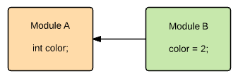
Figure -5 Module B knows about Module A
How do we hide variable "color" from Module B and still let Module B use the value stored in variable "color"?
We need to use "setter" and "getter" functions to achieve that. If we use a setter API to set the value stored in "color" variable via a function called "setColor", then, we don't really need to know what the actual variable name is. Hence, when the name of that variable is changed in Module A for some reason, Module B would not be impacted by that.
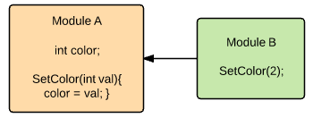
Figure -6 Module B uses the setter function but does not know the name of the variable "color" to set its value.
Setter API is implemented as the following.
void SetColor(int var){
        color = var;
}
If in the future, let's say the name of the variable "color" is changed to "backgroundcolor", only the implementation of SetColor should be changed and Module B does not need to change. Therefore, impact of change in Module A to other firmware modules is minimized.
Same thing applies to retrieving variable content from other firmware modules. One needs to implement getter APIs to provide encapsulation. If Module A implements the following getter API,
int GetColor(void){
return color;
}
Then, there is no need for Module B to know what the actual name of the "color" variable is. Module B directly uses GetColor() API.
It is not the only reason why we need to hide data. The other important reason to hide data is to protect other modules from accessing any data in other modules arbitrarily. They should only access the data provided by public setter/getter APIs rather than directly accessing global variables of other modules. Therefore, the design of Module A dictates which variables should be exposed to the other modules.
ExtensibilityArchitecture should support adding a new feature to the FW. Firmware architecture should make sure separation of concerns is achieved in a way that adding a feature to the application should be seamless and easy thing to do. Modularity, Encapsulation and Low Coupling help achieve do that. If features are implemented as firmware modules, then it is easy to add a feature to the firmware.
How are encapsulation and low coupling related to Extensibility?
If there is low coupling and encapsulation is achieved, then impact of adding a feature to the firmware would be minimized as well. The new module would depend on less number of other modules and there will not be major changes in many other modules.
Scalability and Portability
Architecture should allow the FW to be scalable to various HW sizes (sensor size, etc) and easy migration to another hardware.
To provide that, there should be a hardware abstraction layer (HAL) consisting of hardware (HW) specific firmware modules to isolate hardware initialization and control from other modules. Therefore, each module does not directly access HW registers. They access HW registers through APIs of the HAL layer. This minimizes the impact of HW changes to the rest of the firmware modules since if a HW register changes, only the HAL is updated.
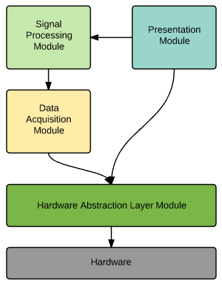
Figure -7 An example of a hardware abstraction layer (HAL) as a module
Following example shows a wrong dependency.
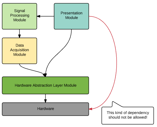
Figure -8 An example to wrong dependency
Dependency from an upper layer should be down to HAL not beyond in order to access any hardware. If this concern is always addressed in implementation, it would be easy to swtch to another hardware or scale hardware easily by only making changes in the HAL.
Data flow
There are well known data flow design patterns in software architectures and one of them could be used in firmware architectures as well depending on system requirements. Most commonly used two patterns are called "Pipes and Filters" and "Blackboards". In "Pipes and Filters" pattern, the data flows from one module to another. In the following example, some data is acquired from hardware by the Acquisition module and pushed to Processing module to get it processed, then the processed data is pushed to Presentation module to show it to a user via Leds, LCD or something of that sort or transfer it to another processor using the available communication peripherals (I2C, SPI, USB, etc). Firmware systems realizing this architecture should at least have one source and one sink and one or more processing stages should exist.
In this context, Pipe is an abstraction of a data transfer mechanism which could be simply passing a pointer to data in a function argument whereas Filter is an abstraction for a processing stage. In the following example, source could be the Data Acquisition module where the data is read from an ADC of some type and sink could be considered as the Presentation module where it sends the data to a HW to be displayed or conveys it to another processor through a protocol.
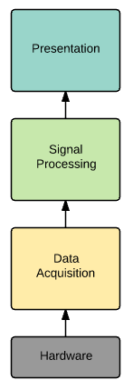
Figure -9 An illustration of Pipes and Filters data flow
In "blackboards" design pattern, data is always written to a shared memory area and used from there. Only the pointers to the shared area are passed to the modules but the data resides in shared memory. Blackboards pattern can be thought of as wires connecting modules to each other since only the pointers are passed. A canonical form of Blackboards pattern is illustrated below.
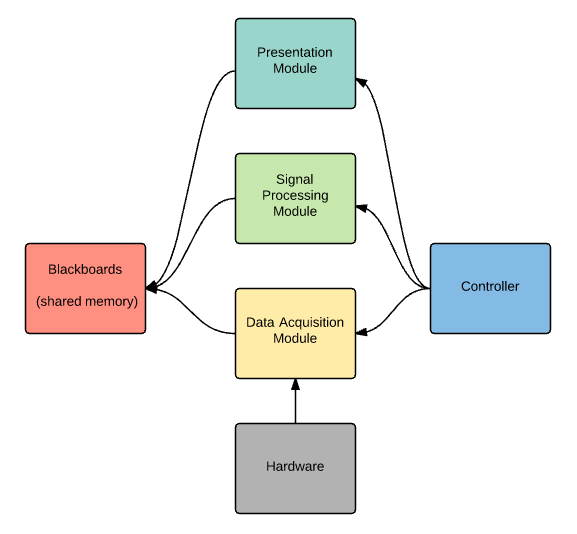
Figure -10 Blackboards pattern
As you can see from Figure-10, Data Acquisition module reads the data from hardware and writes it to the shared memory. Once that is done, the controller passes the pointers to Processing module to read/write from/to the Blackboards and it does the same thing for Presentation module. Therefore, there is a need for a Controller in Blackboards pattern. Note that Controller gets to decide which API will be called from which module and in which order. Therefore, not only data flow but also execution flow is controlled by the Controller in this case.Fundamental idea behind Blackboards pattern is that several Expert modules contribute to solving a problem by processing the data in the shared memory. This decouples the FW modules from each other and allows adding/removing modules to the project easily. The Controller entity coordinates execution of the Expert modules based on high-level decisions.
Re-usability
Architecture should allow or promote module re-usability to keep amount of changes from one product to another.
Communications
A good architecture defines which modules own data, which modules have access, what is life-cycle of data and what is the format of data.
Fault tolerance (robustness)
Scope of faults and desired actions should be clearly defined.
Testability and Verifiability
Modules should be testable and verifiable. That means, the external (customer) requirements of a project should be de-composed into pieces (internal firmware functional requirements) that can be implemented as features of the modules and the modules then should be tested to verify correctness of functionality or features to see if the external requirements are met.
Unit test driven firmware development provides the tool for verification of functionality as long as the requirements are well decomposed and distributed to modules. Once that is achieved, then, integration testing should be carried out to verify performance as well.
Nightly regression (continuous integration) testing using build system tools such as (Jenkins, Bamboo, etc), build system sanity checks (to see if the interface definitions break the rules), static code analysis tools, and unit test automation should be part of the firmware development cycle to early catch the issues.
Maintainability
Developers should follow a coding convention, care about their API namings, do proper amount of commenting and try write readable code rather than writing obfuscated codes with fancy looking function pointers and such unless really necessary.
Architecture should be easily documented with event or timing diagrams, flowcharts, state machines, class diagrams etc.


- Comments
- Write a Comment Select to add a comment

them.
"The event driven systems are comparatively simpler." ... simpler than what?


Hi,
The figures still seem to be missing. I used the FireFox browser as well as the Internet Explorer browser. Neither browser displayed the missing figures as of October 11, 2016.
Now a days if you google for embedded FW principles you will get ton of papers, but nobody explain with example.
Very nice article. Maintaining clean and and good firmware architecture has been a constant struggle in my life and i think that is going to be there for me, but this article is a great help for me, and i happened to read at right time when i am entangled in a huge chunk of spaghetti code.
To post reply to a comment, click on the 'reply' button attached to each comment. To post a new comment (not a reply to a comment) check out the 'Write a Comment' tab at the top of the comments.
Please login (on the right) if you already have an account on this platform.
Otherwise, please use this form to register (free) an join one of the largest online community for Electrical/Embedded/DSP/FPGA/ML engineers:


