


Cortex-M Exception Handling (Part 1)
This article describes how Cortex-M processors handle interrupts and, more generally, exceptions, a concept that plays a central role in the design and implementation of most embedded systems. The main reason of discussing this topic in detail is that, in the past few years, the degree of sophistication (and complexity) of microcontrollers in handling interrupts steadily increased, bringing them on a par with general-purpose processors.
This first part of the article focuses on general information, and then on what happens before an exception request is accepted by the processor and its handling begins. The second part of the article will discuss instead the Cortex-M behavior after an exception request is accepted and provide additional details.
OVERVIEW
Like it happens in many other processors, the Cortex-M also handles other kinds of events, such as faults, in the same way as interrupts, that is, in a unified way. All these events are collectively referred to as exceptions. For this reason, in the following we will, more generally, talk about exception rather than interrupt handling.
To get started, let us examine more in detail what exceptions are, and describe their purpose and origin. A property that all exceptions have in common is that their occurrence may disrupt the normal instruction execution flow and direct the processor to execute a fragment of code associated with them, called exception handler.
In the statement above we say “may” because the mere occurrence of an exception is necessary, but not sufficient, to ensure that the processor will handle it immediately, if at all. In fact, as it will become clearer in the following, there is a long way between the origin, or source, of the exception — which is often hardware-related — and the first action visible to software, that is, the execution of its handler. The main categories of exceptions are described in the following.
Interrupt requests
This kind of exception is raised by a peripheral device, in order to signal to the processor, and eventually to the software, the occurrence of an event of interest concerning the device itself. For instance, an Ethernet controller may use an interrupt request to indicate that one or more network frames have been received.
On Cortex-M processors, interrupt requests can also be issued by means of a software action. In this case, they are often referred to as software interrupts. Regardless of their origin (hardware or software) interrupt requests are all handled in the same way and no further distinction will be made on this aspect.
Like ordinary interrupt requests, also Non-Maskable Interrupt (NMI) requests can be issued by either hardware or software. The main difference is that their priority is extremely high, namely, the highest in the system below the reset exception. The concept of exception priority plays a central role in Cortex-M exception handling and will be examined in detail in the following.
For the time being, it is enough to say that a higher exception priority ensures that the handling latency — that is, the time elapsed between the occurrence of an exception and the execution of its interrupt handler — decreases because the processor handles this exception in preference of others.
Also belonging to this category are two more exceptions that are generated within the processor itself, rather than coming from external peripheral devices. They are:
- The SysTick exception, generated periodically by the 24-bit count-down system timer and often used by operating systems to drive time slicing. If needed, the same exception can also be issued by software.
- The PendSV exception, which can only be triggered by software. It is often used by operating systems to indicate that a context switch is due and perform it at a future time, when no other exceptions must be handled.
Faults
Generally speaking, all faults are generated as a consequence of an abnormal event detected by the processor, either internally or while communicating with memory and other devices. These events are of great interest (and concern) to software because most often they indicate serious hardware or software issues that likely prevent the software itself to continue with normal activities. More specifically, the following kinds of fault are foreseen in Cortex-M processors.
- UsageFault. This fault occurs when an instruction cannot be executed for various reasons. For instance, the instruction may be undefined or may contain a misaligned address that prevents it from accessing memory correctly. For divide instructions, another reason for raising a UsageFault is an attempt to divide by zero.
Some of the above-mentioned fault sources (like divide by zero) can be masked in software, that is, the processor can be instructed to just ignore them without generating any fault, whereas others (such as encountering an undefined instruction) cannot, for obvious reasons. - BusFault. This fault is generated when an error occurs on the data or instruction bus while accessing memory. In other words, it can be generated as a consequence of an explicit memory access performed by an instruction during its execution, and also by fetching an instruction from memory.
On the other hand, this fault does not cover errors generated by the memory protection mechanisms, which instead trigger a
MemManage fault, to be discussed next.
It should also be noted that, being the Cortex-M a memory-mapped input-output (I/O) architecture, whenever we refer to a “memory” address here and in the following, we actually mean an address within the processor’s address space that may refer to either a memory location or an I/O register. - MemManage. This fault occurs when a memory access is blocked by the memory protection mechanism. An optional Memory Protection Unit (MPU) provides a programmable way of protecting memory regions against data read and write operations, as well as instruction fetches, also depending on the current privilege mode of the processor.
Even on processors not equipped with a MMU, hardware may still set forth some predefined, and non-programmable, constraints on memory accesses. For instance, the processor forbids instruction fetch operations from address space areas that contain I/O registers.
A special kind of fault is HardFault. It can be generated for two different reasons. First of all, the processor generates a HardFault when an error occurs during exception processing, thus disrupting the normal exception handling flow.
The second reason why a HardFault can be generated is a mechanism known as fault escalation. Under certain conditions this mechanism may transform, or escalate, some other exceptions into a HardFault. More details, as well as a few examples of how this mechanism works, will be given in the second part of this article.
Supervisor call (SVC)
This exception is raised by the execution of a SVC assembly instruction. It is commonly used as a convenient way to enter the operating system kernel and request it to perform a function on behalf of the application.
Reset
This exception is triggered by the processor power-up sequence or a warm reset. It is handled as other exceptions for the most part, except that instruction execution can stop at an arbitrary point. As it will be better explained in the second part of this article, a few other aspects are different, too, for instance the processor execution mode.
EXCEPTIONS PRIORITY IN THE CORTEX-M
Long gone are the days in which, when using a typical microcontroller, accepting and handling an exception was an “all or nothing” affair mainly depending, in the case of interrupts, on whether or not they were enabled. As shown in the figure below, in the Cortex-M the decision of whether or not an incoming exception request should be accepted and become active, that is, whether or not the processor immediately starts handling it, depends on a number of rather complex factors.
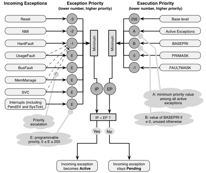
More specifically:
- On one hand, each kind of exception (listed on the left of the figure) has its own exception priority value. Somewhat counterintuitively, numerically lower numbers correspond to higher priorities. Priority values can be either fixed or programmable. For instance, the priority of a NMI request is always −2, whereas for interrupt requests the priority can be set to any non-negative value between 0 and 255 included.
Programmable priority values are denoted as E in the figure and it should be noted that, as further explained later, depending on the processor implementation, only some high-order bits of these values may be significant.
As also shown in the figure, when there are multiple, simultaneous incoming exceptions, the one with the numerically lowest value (corresponding to the highest priority, as stated above) prevails on the others and determines the incoming exception priority IP.
When there are two or more simultaneous, incoming exceptions with the same priority, the one with the numerically lowest exception number, a unique and fixed number assigned by the processor to each exception, takes precedence. - On the other hand, the processor keeps track of its current execution priority EP. As depicted on the right part of the figure, the execution priority is the minimum of several values, namely:
- The base level of execution priority, which is one more than the highest priority value supported by the processor, 256 in this case.
- The minimum priority value A among all exceptions that became active in the past and whose handling has not been completed yet, if any.
- The value of the 8-bit register BASEPRI, if it is not zero. BASEPRI can only be set to non-negative values.
- The values 0 and/or −1, depending on whether or not the 1-bit registers PRIMASK and/or FAULTMASK are set, respectively.
The values of IP and EP are then compared to determine if the incoming exception must become active or it must stay pending. In particular, the incoming exception becomes active if IP < EP (strictly) and stays pending otherwise. Afterwards:
- When an incoming exception becomes active, the processor starts handling it immediately, through a mechanism further detailed in the second part of this article. As a consequence, if the processor was already handling an exception, the handling of the new exception is nested into the old one. In other words, the processor temporarily stops handling the old exception in favor of the new one, and will go back to it at a later time.
- Otherwise, the incoming exception stays pending. The processor will evaluate the possibility of making it active whenever EP changes, possibly becoming numerically higher than it was. The evaluation is still carried out as described above, also incorporating into IP the priority of any further exception request that arrived in the meantime. For instance, re-evaluation takes place when the handling of an active exception terminates, because this may increase the value of A and, in turn, of EP.
Stating again the same concept more informally, programmers can set BASEPRI, PRIMASK and/or FAULTMASK to postpone handling of some exceptions. For instance, setting BASEPRI to a non-zero, positive value T prevents the processor from accepting any exceptions whose priority value IP is above that threshold, that is, IP ≥ T, unless priority escalation takes place.
Priority escalation, which will also be one of the subjects of the second part of this article, is a mechanism that may raise the priority of some faults to the same priority of HardFault. This is indicated by the dashed arrows in the figure. Since the HardFault priority is fixed to −1, no settings of BASEPRI can have any effect on its acceptance.
In extreme cases, it is also possible that that processor encounters an unrecoverable exception. Generally speaking, this takes place when an exception occurs while the processor is already handling another exception, priority escalation cannot be applied, and the processor is neither able to continue execution of the current exception handler, nor start handling the new exception. As a consequence, the processor enters a special lockup state and stops normal instruction execution completely.
For the sake of completeness, even though a thorough discussion of this aspect is beyond the scope of this article, we must also mention that the comparison between IP and EP is possibly affected by a processor feature known as priority grouping.
In short, it is possible to instruct the processor to “mask off” some low-order bits of the priority value so that priority levels that are distinct in principle “look the same” in the comparison. In other words, neglecting some low-order bits of the priority value groups together exceptions whose priorities may differ in those low-order bits, but are the same in the others.
As a result, handlers corresponding to exceptions with different priorities, but belonging to the same group, will not be nested into each other.
GATHERING FURTHER DOCUMENTATION
At the time of this writing, the Cortex-M family of processors comprises several members, namely, the Cortex-M0, M0+, M1, M3, M4, and M7. As can be expected, the main differences among them are in the area of processing power, namely clock speed and instruction set capabilities.
As such, gathering information about a specific member of the family implies perusing more than one manual or data sheet. To further complicate the matter, it is well known that ARM itself does not physically make chips, and leaves to chip makers some freedom to configure several features of Cortex-M processors for a specific implementation.
In increasing order of specificity, the main sources of information to gain a thorough knowledge about the Cortex-M family are:
- The official ARM documentation, which is the most comprehensive and authoritative source of information about the Cortex-M family as a whole, because it comes directly from the designers of the processor itself. Depending on the processor, the architecture is specified in:
- Version 6 of the ARM architecture, Microcontroller profile (ARMv6-M), described in the ARMv6-M Architecture Reference Manual (Cortex-M0, M0+, and M1).
- Version 7 of the ARM architecture, Microcontroller profile (either ARMv7E-M or ARMv7-M, depending on whether or not Digital Signal Processing (DSP) instructions are implemented), presented in the ARMv7-M Architecture Reference Manual (Cortex-M3, M4, and M7).
- Further information about specific members of the family are available in other manuals, still published by ARM. For instance, in-depth information about the Cortex-M3 are provided in:
- The Cortex-M3 Devices Generic User Guide. It is much shorter than the Architecture Reference Manuals referenced above and focuses only on the specific features of the Cortex-M3, with respect to the Cortex-M family as a whole.
- The Cortex-M3 Technical Reference Manual. This manual contains the ultimate technical information about a specific revision of the Cortex-M3 core. Moreover, it contains details about some processor features not covered by the Generic User Guide, for instance, debugging-related components, or macrocells.
- Last, but not least, it is important to distinguish between a Cortex-M processor (as supplied by ARM) and a Cortex-M device (as implemented by a specific vendor on a specific chip it produces). The distinction is important because several choices about how the processor will “look like” are made at implementation time.
These choices are called implementation options in the Generic User Guide and configuration options in the Technical Reference Manual. Configuration options mainly control which optional processor components are available in a specific implementation, whereas implementation options are related to finer, inner details of the processor itself, for instance, how many interrupt lines, or sources, it is able to handle.
Unlike the previous ones, device-related manuals are published by the chip vendor rather than ARM. For the sake of example, all details about how the Cortex-M3 processor has been implemented in the NXP Semiconductors LPC176x range of microcontroller are available in the LPC176x/5x User Manual.
Further information from the chip vendor is usually made available in the Product Data Sheet, like this one, which applies to the LPC1763 through LPC1769. However, its main focus is on packaging and electrical characteristics of the chip. For this reason, data sheets are of most interest to hardware designers rather than software developers.
In order to better explain how and why all these sources of information are important to gain a thorough (and correct) understanding about how a certain implementation of a member of the Cortex-M processor family works, let us consider a specific example, concerning how many bits are significant in an exception priority value.
There is no need to highlight how important this information is because it determines the ability of the processor to “tell apart” two distinct priority values we may use in our code and differ only in a few low-order bits. In turn, this deeply affects several aspects of exception handling, like nesting.
Considering the LPC1768 microcontroller, incorporating a Cortex-M3 processor, about this topic:
- The ARMv7-M Architecture Reference Manual (which applies to the Cortex-M3) says that the number of priorities is an implementation-defined power of two in the range from 8 to 256. In any case, priority values are always represented using 8-bit fields, of which only high-order bits may be significant.
- Both the Generic User Guide and the Technical Reference Manual of the Cortex-M3 repeat the same concept. Moreover, the Generic User Guide remarks that the number of significant priority bits is an implementation option.
- Eventually, the LPC17xx User Manual states that the LPC1768 implementation of the Cortex-M3 supports 32 distinct priority levels, that is, the 5 high-order bits of 8-bit priority fields are significant. The others are ignored on writes and read as zero.
- For the sake of completeness, the Product Data Sheet also mentions, in passing, that 32 interrupt priority levels are available for use.
It is also worth mentioning that, recently, additional high-quality literature about Cortex-M processors became available. For instance, this book is a thorough and insightful description of the Cortex-M3 and M4. Although it is not official ARM documentation, it is nonetheless a very authoritative guide because it has been written by one of the engineers who helped develop those processors.
Moreover, instead of focusing only on the processor itself, it also contains information about other relevant topics, like software development toolchains and operating system support.


- Comments
- Write a Comment Select to add a comment

To post reply to a comment, click on the 'reply' button attached to each comment. To post a new comment (not a reply to a comment) check out the 'Write a Comment' tab at the top of the comments.
Please login (on the right) if you already have an account on this platform.
Otherwise, please use this form to register (free) an join one of the largest online community for Electrical/Embedded/DSP/FPGA/ML engineers:


