


Metal detection: beat frequency oscillator
Plan
- Introduction
- Theory
- Electronics
- Software
- Tests
- References
- Next part: building the detector
1. Introduction
This article discusses the implementation of a beat frequency oscillator (BFO) stage for metal detector. While they are mentioned here and there, the article does not detail other important electronic stages such as the power supply, and user interface, the coil or the detector frame. I may write other articles on these topics, and other detection methods.
Before starting, note that a GIT repository containing the materials related to this article is available here:
https://github.com/texane/metdet
For this article, I am using commit ec23c5692accf609b12fa997f7e966d54dffc4d9
2. Theory
To my knowledge, any practical metal detection technique relies on measuring the direct or indirect effects that a metal object has on a magnetic field. There are several ways to do so. One consists in measuring the inductance variation of a coil subject to a varying magnetic field.
First, let see how inductors interact with metal objects. An approximation to compute the inductance of an air core coil is given by:
L = u * N^2 * A / l
Where:
- L the coil inductance in Henry,
- u the absolute magnetic permeability,
- N the number of turns,
- A the coil area in square meters,
- l the coil length in meters.
What is important is that inductance depends on the magnetic permeability. There are 2 ways the permeability can vary:
- the permeability is increased because of the presence of iron objects. It is why iron based cores are used in transformers. Said otherwise, the inductance is increased by iron presence,
- the permeability is decreased due to Eddy currents induced in non ferrous objects. The alternating magnetic field creates small currents in these objects, which in turn produce a magnetic field which opposes to the original field. In that case, inductance is decreased.
In both cases, the inductance is changed. What is interesting is that the sign of the change can be used as a basic discriminator to distinguish between ferrous and non ferrous objects. This must be mitigated as the shape of the object plays an important role, especially its 'flatness'.
As a note, some people consider the Eddy current effect as shorted turns in the inductance coil. I do not understand this, so I prefer figuring Eddy currents them as creating magnetic fields that oppose to the original magnetic field, decreasing the permeability and thus the inductance of the original coil.
Back to the BFO method. The idea is to measure the frequency of a LC oscillator. By fixing the capacitance C, any change in the oscillator frequency means the inductance L has changed due to some metal object.
The oscillator frequency is a trade-off of importance. A low frequency (10KHz) is best to penetrate the soil. A high frequency is best to induce Eddy currents. Also, the higher the frequency the higher the resolution for the same period of integration time during counting. This circuits uses the 100KHz range as do most BFO designs.
3. Electronics
The circuit schematics:
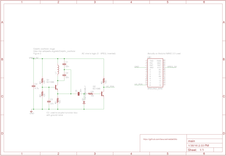
LC oscillator stage
This circuit first stage consists in a Colpitt oscillator. The coil of the oscillator produces a varying magnetic field which changes the inductance of the coil according to the principles mentioned previously. The oscillator signal is then conditioned to logic levels and fed to a micro-controller digital IO for further frequency counting.
For more information on Colpitt oscillators, 2 good references:
https://en.wikipedia.org/wiki/Colpitts_oscillator
http://www.learnabout-electronics.org/Oscillators/...
The oscillation frequency is given by:
f = 1 / (2 * PI * sqrt(L * C1 C2 / (C1 + C2)))
I chose C1 = C2, thus:
f = 1 / (2 * PI * sqrt(L * C/2))
C is fixed to 22nF. L depends on the coil, and is in the range 200 to 300 uH. It gives a frequency range between 80KHz and 110KHz which works fine in practice.
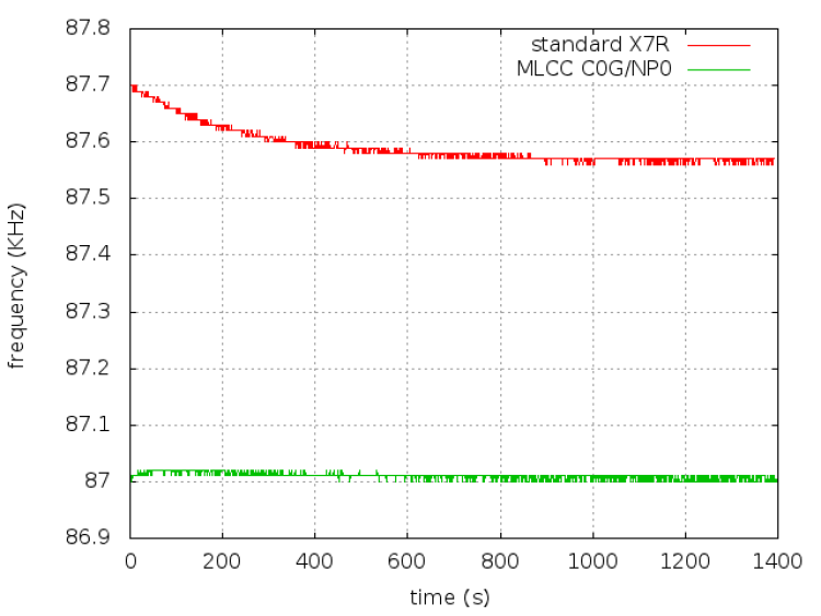
On capacitor quality
During the tests, I noticed a change of frequency over the time even when the detector did not pass over metal. I had to recalibrate the detector often during the first few minutes of use. I tracked this issue down to the capacitors themselves. I initially used standard X7R ceramic capacitors, whose value drifted due to temperature change. I replaced them by MLCC capacitors. While expensive (2 euros per capacitor, Farnell ref: 2395768), it largely improved the situation. Below a graph comparing frequency over time with the 2 capacitors models.
A good reference on this topic:
https://www.maximintegrated.com/en/app-notes/index...
Frequency counter stage
Note that many BFO metal detectors were designed in the 80s with analog stages to detect frequency changes. Typically, they are based on heterodyning, ie. mixing the oscillator signal with another reference oscillator signal of nearly the same frequency. By low passing the resulting signal, the frequency difference is obtained. Frequencies are computed so that the difference falls into the audible range. The end signal is then fed to a speaker. More information can be found here:
https://en.wikipedia.org/wiki/Heterodyne
Now, digital logic is well adapted for counting especially in the BFO frequency range. I chose an Arduino board for this task, whose software is detailed latter. Also, this board is used for other purposes such as user interface and LiPo battery monitoring.
Using digital logic does not come for free and requires the oscillator signal to be converted to digital logic levels (ie. 0V - 5V). For this purpose, I use a NPN transistor based inverter, since the same transistor is already used by the oscillator stage. Note that depending on the coil inductance, the oscillator signal amplitude may be such that it is not necessary to condition it. In my case, conditioning is needed as I want to test different coils.
The following picture shows an example of oscillator signal, and the corresponding logic signal:

This digital signal is then fed to the microcontroller PD5 digital input, used by the software counter software.
4. Software
The software core consists of a frequency counter implemented by the hfc_xxx routines, available here:
https://github.com/texane/metdet/blob/master/bfo/s...
TIMER1 is used to count the rising edges of the PD5 digital input. TIMER2 is used to wait for a precise time (100ms). Note that both timers are extended by software variables and overflow interrupt handlers due to their limited capacities.
At the end of the integration time, the counter value is captured. If its value differed from the previous one, frequency thus inductance has changed and a metal object is detected. A delta allows to set sensitivity.
The current implementation uses the serial port to print the counter value changes.
5. Tests
The following video shows a lab test. It uses a 10cm diameter coil, whose inductance is around 290uH. The laptop behind prints the counter value when frequency change is detected as a metal object is passed over the coil. The distance from the coil is around 10cm.
6. References
Inside the metal detector, second edition, G. Overton, C. Moreland
geotech forums, http://www.geotech1.com
http://www.geotech1.com/pages/metdet/info/bfotheor...
7. Building the detector


- Comments
- Write a Comment Select to add a comment
Thanks for this informative writeup! As electronics engineer i planed to to exactly the same and looked with vague search terms for inputs... just to find your article with 100% coverage of my idea. Nice! :)
One question i have to the coil: I want to make a detector for Aluminum (arrows) 1-4cm below ground, but all facing away from the searcher. So i thought: If i make a rectangular coil like 50cm x 5cm the arrow (itself around 70cm long) the arrow "fills" quite a lot of the area within / below the coil and the f-change would be even greater.
Now... As i have absolutely ZERO knowledge about metal detecting, is the idea of a non-circular coil even smart / feasible?
Thanks for inputs and comments! Willing to learn. ;)
To post reply to a comment, click on the 'reply' button attached to each comment. To post a new comment (not a reply to a comment) check out the 'Write a Comment' tab at the top of the comments.
Please login (on the right) if you already have an account on this platform.
Otherwise, please use this form to register (free) an join one of the largest online community for Electrical/Embedded/DSP/FPGA/ML engineers:


