


Metal detection: building the detector
Introduction
Before starting, you may want to read this post describing the BFO stage://www.embeddedrelated.com/showarticle/911.php
I have detailed the implementation of a BFO stage for detecting metal. Now it has been validated on the bench, the next step is to integrate it in a stand alone instrument for testing on the field. A few things have to be done to reach this goal:
- make a PCB for the electronics,
- house the PCB in a box,
- add a power supply,
- make a frame to hold everything together.
Ghetto mode turned on ... I am using parts lying here and there, so do not expect an engineering masterpiece here :)
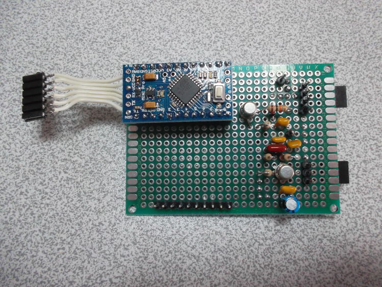
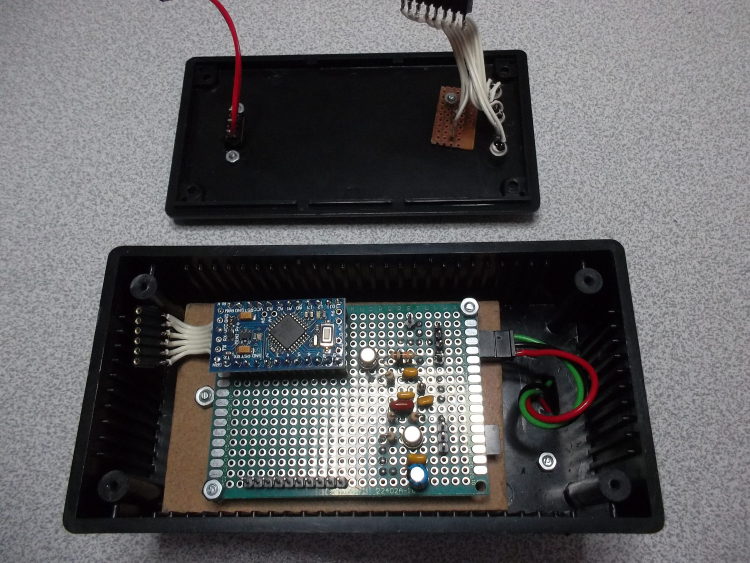
PCB
The first thing is to leave the breadboard for a PCB. Given the size and simplicity of the circuit, I chose to use through hole components on a 50x70mm prototyping PCB. The dimensions are a bit large, but I wanted to have room for more electronic stages. These ones are of very good quality:
http://www.ebay.com/itm/10PCS-Double-Side-Prototyp...
Also, I switched from the Arduino Nano to the Mini. The reason is to reduce the power consumption by removing the FTDI chipset, which I use mostly for development purpose. Also, it reduces the board size and cost. An external FTDI cable will be used if needed. You can find Arduino Nano 5V here:
http://www.ebay.com/itm/1x-New-Mini-Pro-atmega328-...
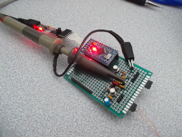
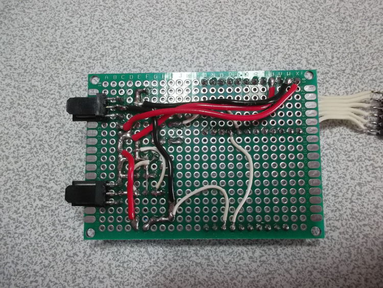
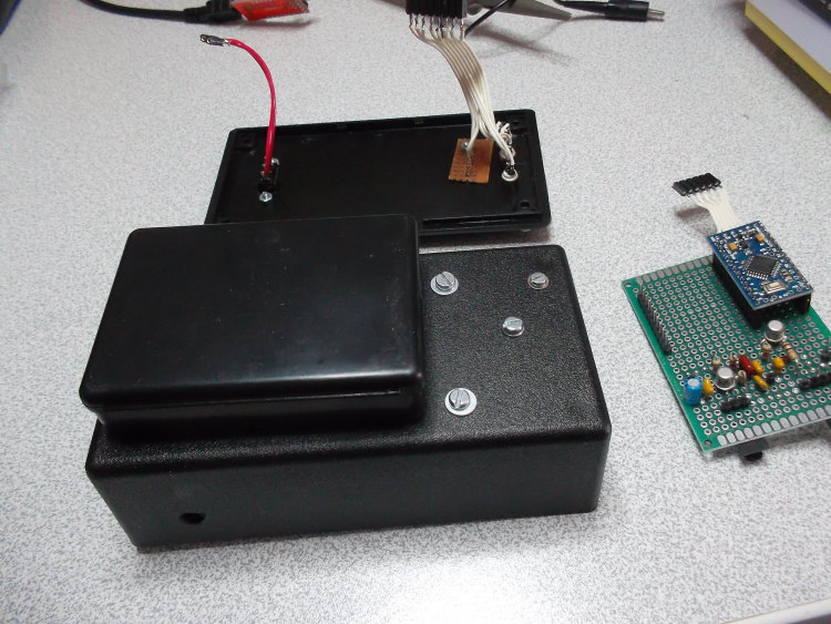
The end result:
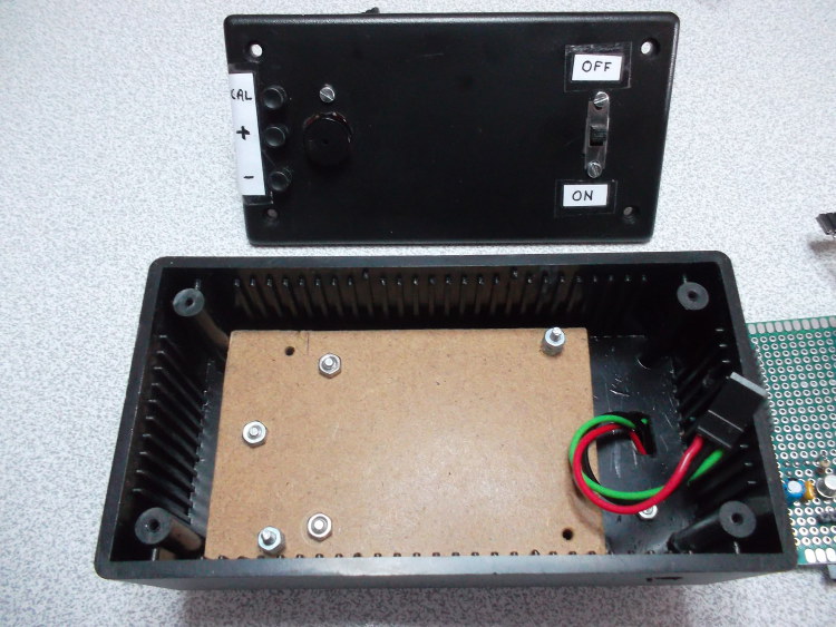
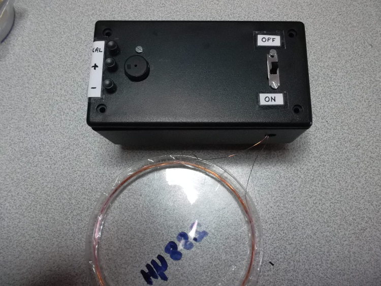
Housing and control box
This box first purpose is to protect the electronic components from ambient particles (dust, rain ...). Also, it is the user interface and hosts controls and reporting mechanisms.
I used a 130x70x40mm ABS box. I like these ones because they are easy to machine. One drawback is that additional shielding is needed if appropriate, which is not our case given the signal amplitudes. Also, while it will handle light rain, these boxes are not waterproof.
I did not fix the PCB on the box. Instead, I mounted it on an intermediary panel. This panel can be modified or changed if the PCB changes, let say for another circuit with different mounting holes.
For the control parts, I added 1 power switch, 3 buttons (calibration and sensitivity) and one piezo buzzer. My laziness set apart, I found a buzzer more interesting than LEDs or LCDs for this application. First, I prefer acoustic than visual interfaces (ie. my eyes suck). Also, more information can be encoded than in a LED, given you can modulate both in time and frequency.
Finally, note that all connections from the box to the PCB can be removed without a soldering iron.
The result:
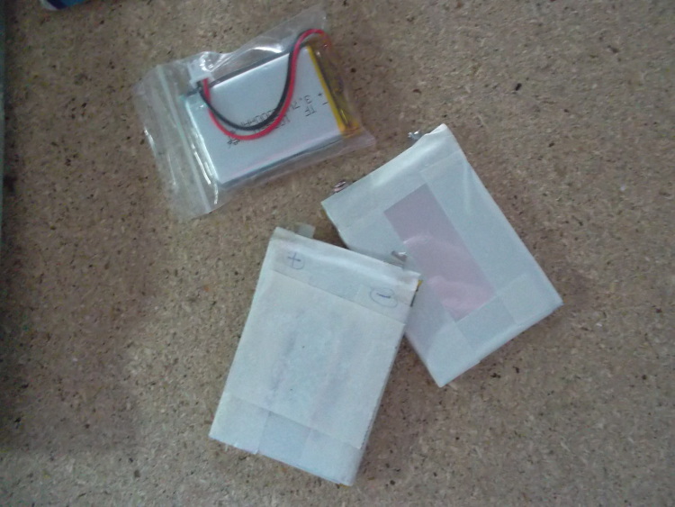
Power supply
The electronics is powered by an on board 5V LDO. It means that the supply must be more than 5.5V or so. I chose to put 2 3.7V LiPo cells in series. The main reason is that I have saved plenty of them from the trash. They are low cost, dense, allow for high discharge currents and can be recharged.
Using LiPo requires added precautions. For instance, individual cell voltage should not drop below a certain threshold, and additional code has to be added to inform the user of this situation. Also, a safe design should include bypass and protection diodes, which is not the case in my circuit.
As a side note, be careful when retrieving LiPo cells from devices. It can be an experience in itself ... Also, store them safely. A good practical guide on this topic:
http://www.rogershobbycenter.com/lipoguide/
To gain some space in the electronics box, I packaged the cells in a separate plastic box used by Radiospare to ship their components. This box is fixed with screws on the other one:
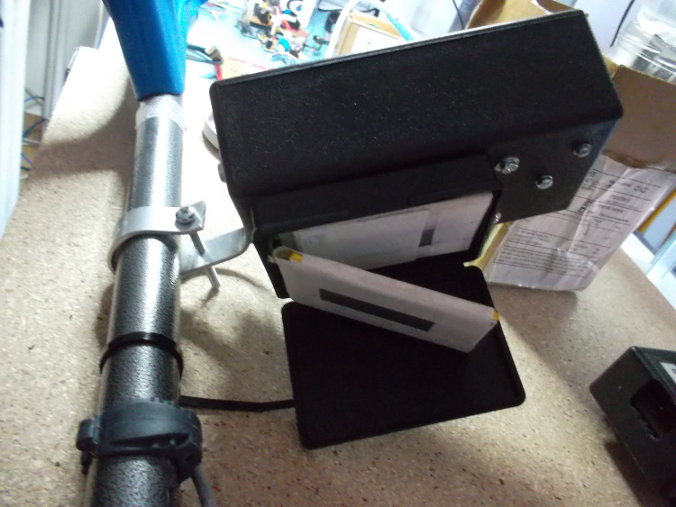
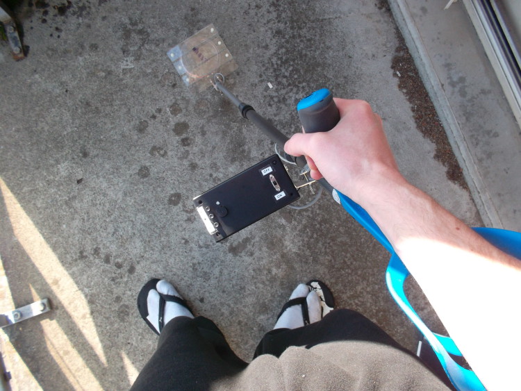
Detector frame
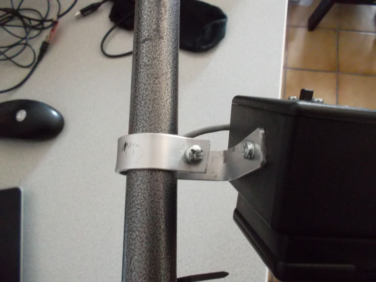
A crutch is very well adapter for this task, and I have some at home. I did not want to drill in the crutch itself so it can still serve its original purpose. Instead, I machined an aluminum tube of the same diameter. Also, I created some parts to fix the control box and the coil head. As my 3D printer is not yet ready, I sticked to wood and bent aluminum for the joints.
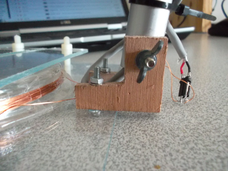
The coil is sandwiched between Plexiglas sheets and nylon nuts and bolts hold them together. This is to avoid magnetic interference. Also, it is not prone to corrosion.
The end result:
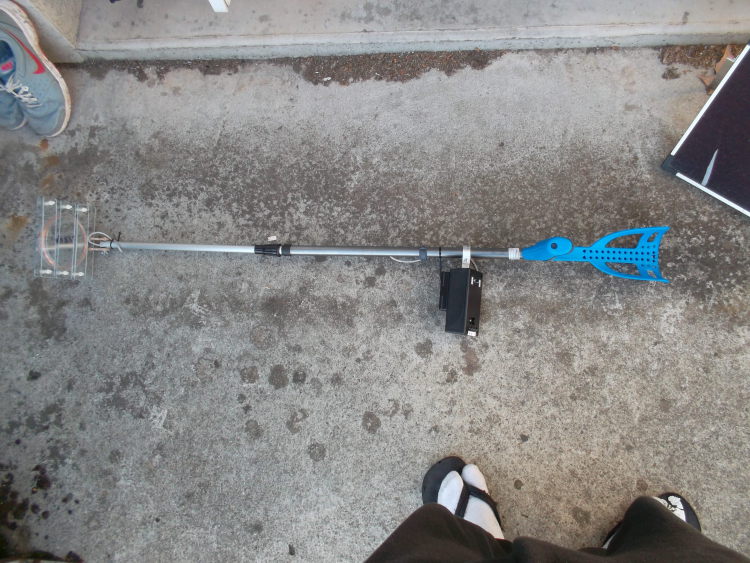
Conclusion
I did not want to spent too time as I am working on a 3D printer which will ease this kind of work. The detector is not elegant, yet very usable. The main drawback is that the coil head is not waterproof. Now, let's go hunt some treasures !


- Comments
- Write a Comment Select to add a comment
Thanks for the great blog. I wonder about the coil, however.
For performance, I would expect that the coil would be one of the most important components. But all I found about the coil was from your previous post: "It uses a 10cm diameter coil, whose inductance is around 290uH."
Where did the coil come from? Did you wind it yourself? How many turns?
I assume there is nothing ferrous near it (air core). Is that true?
How does the diameter affect the performance? I would suspect that the larger the coil, the less sensitive it might be for small objects. But a smaller coil would cover less area. Is my thinking correct? What are the other trade-offs with coil size?
Thanks again,
Mark

Thanks for your feedback. I plan to write another post on coils, with experiments and notes. That is why I did not cover this topic. For now, here is my answer.
The coil is very important actually. I wound the coil myself. It is an air core. It is approx. 40 turns of 0.20mm diameter wire. The coil diameter is 110mm. The most important thing is that the oscillator frequency is around 100KHz. Precise winding is not important, but it is better if turns are tight and solid. Also, the coil must not move and stay in the same plan during the whipping.
As a rule of thumb, the depth achievable by a given coil is approx. its diameter. So the larger, the deeper. But not adapted for small objects. That is why you use pinpoint detectors, with small coils of 30mm diameters.
Note that more turns means higher resistance. So the series resistor may have to be adapted.
Another thing to consider is coil shielding.
Hope it helps, stay tuned for the coil article :)
Hi Fabian,
I'm a senior electrical engineering student. Part of my senior project requires that I build a metal detector so I'm considering building a detector based on your BFO design. Before I start buying parts, I have a few questions for you or any one else that has the knowledge to answer:
1) Is there a way to build this device to remove the need for re-calibration, or at least mitigate that need?
2) Ideally, I would prefer a design that does not require any re-calibration. Do you know of any types of metal detectors require little to zero amounts of calibration?
3) If I build the detector exactly as described by you, how often must the device be calibrated?
Thanks a lot!
-Kyle
Hi Fabian,
Could standard 9V alkaline batteries be used to power this circuit? If not, is there a way to change the design so uses 9V alkaline batteries become feasible?
Thanks again,
Kyle
To post reply to a comment, click on the 'reply' button attached to each comment. To post a new comment (not a reply to a comment) check out the 'Write a Comment' tab at the top of the comments.
Please login (on the right) if you already have an account on this platform.
Otherwise, please use this form to register (free) an join one of the largest online community for Electrical/Embedded/DSP/FPGA/ML engineers:


