





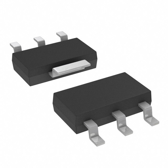
IFXBTS4140NHUMA1
Overview
The BTS4140NHUMA1 is a smart high-side power switch in a compact SOT-223 package, designed to drive loads up to 200mA. It operates over a wide voltage range of 4.9V to 60V and features integrated protection against short circuits, overloads, and overvoltage events. This AEC-qualified N-channel driver is specifically engineered for automotive and industrial applications where reliability and electromagnetic compatibility (EMC) are critical.
Why Choose This Part
The BTS4140N offers a very low standby current of 10uA, making it ideal for battery-sensitive applications. Its integrated thermal shutdown with auto-restart and current limiting ensures robust performance without needing external fuses or complex protection circuitry.
Applications
Key Specifications
Getting Started
When designing with the BTS4140N, ensure adequate PCB copper area around the SOT-223 package pins for thermal dissipation. The device uses a current-controlled input, allowing it to be interfaced with logic-level signals via a series resistor. Engineers should verify the negative output clamp voltage when switching inductive loads to ensure it meets the design requirements for flyback protection.


