



EmbeddedRelated.com
Jacob Beningo
Live online course · Jacob Beningo
AI for Embedded Developers
$100 off for EmbeddedRelated readers until Dec 6 · 5 live sessions, Dec 7-11
Discount ends in
24days 14hrs 45min 49sec
Learn More →
LT1719CS6#TRMPBF

ADILT1719CS6#TRMPBF

Analog Devices Inc.
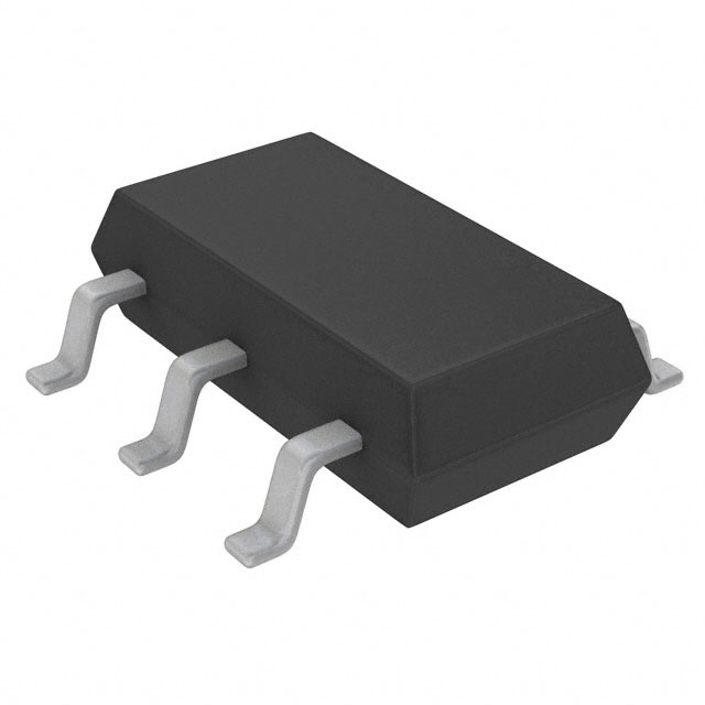
Comparator Standard (General Purpose) CMOS, Rail-to-Rail, TTL TSOT-23-6
NRND25,827 in stock

Overview

The LT1719 is a high-speed, single-channel comparator designed for low-voltage operation between 2.7V and 6V. It features a fast 13ns propagation delay and rail-to-rail outputs that are compatible with CMOS and TTL logic levels. This device is optimized for systems requiring fast signal processing with minimal power consumption in a compact TSOT-23-6 package.

Why Choose This Part

The LT1719 offers an excellent speed-to-power ratio, providing 13ns response times with a maximum quiescent current of 9mA. Its rail-to-rail output swing ensures maximum signal integrity when interfacing with low-voltage microcontrollers and FPGAs. Additionally, the high CMRR of 65dB and PSRR of 80dB provide robust performance in noisy mixed-signal environments.

Applications

High-Speed Differential Line Receivers
Translating differential signals into clean CMOS/TTL logic levels in high-speed data paths.
Zero-Crossing Detectors
Utilizing the 13ns propagation delay for precise timing in power monitoring and frequency measurement.
Threshold Detectors
Accurate voltage monitoring in battery-powered systems with a maximum 2.5mV input offset voltage.
Clock Regeneration
Restoring degraded clock signals in digital systems while maintaining low jitter and fast edge rates.

Key Specifications

Type Standard (General Purpose)
Hysteresis 7mV
Output Type CMOS, Rail-to-Rail, TTL
Mounting Type Surface Mount
Package / Case SOT-23-6 Thin, TSOT-23-6
CMRR, PSRR (Typ) 65dB CMRR, 80dB PSRR
Number of Elements 1
Operating Temperature 0degC ~ 70degC
Current - Output (Typ) 20mA
Propagation Delay (Max) 13ns
Supplier Device Package TSOT-23-6
Current - Quiescent (Max) 9mA
Current - Input Bias (Max) 6uA @ 5V
Voltage - Input Offset (Max) 2.5mV @ 5V
Voltage - Supply, Single/Dual (+/-) 2.7V ~ 6V

Getting Started

When designing with the LT1719, place a 0.1uF ceramic bypass capacitor as close as possible to the supply pins to maintain stability during high-speed switching. Ensure ground planes are used to minimize parasitic inductance, which can cause oscillations in the 13ns transition region. This component can be evaluated using standard SOT-23 breakout boards for rapid prototyping.

Also Consider

MAX9031 Maxim Integrated / Analog Devices - A lower-power alternative suitable for applications where slower propagation delays are acceptable to save board space.