



EmbeddedRelated.com
Jacob Beningo
Live online course · Jacob Beningo
AI for Embedded Developers
$100 off for EmbeddedRelated readers until Nov 1 · 5 live sessions, Dec 7-11
Discount ends in
15days 20hrs 22min 42sec
Learn More →
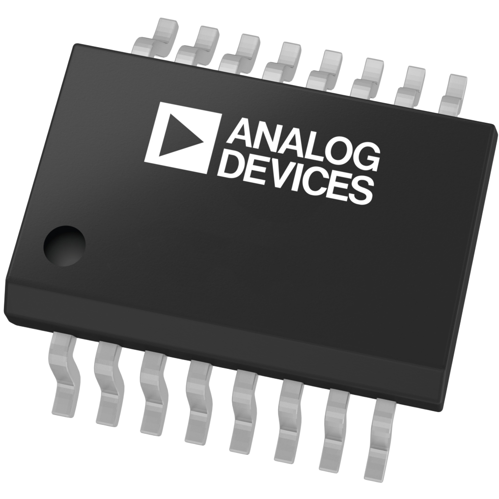
MAX1672EEE+

ADIMAX1672EEE+

Analog Devices Inc./Maxim Integrated
Buck, Boost Switching Regulator IC Positive Adjustable (Programmable) 1.25V (3.3V, 5.5V) 1 Output 300mA 16-SSOP (0.154", 3.90mm Width)
Active517 in stock

Overview

The MAX1672EEE+ is a highly integrated buck-boost DC-DC converter capable of providing a regulated output from input voltages ranging from 1.8V to 11V. It automatically transitions between step-up and step-down modes, making it an ideal solution for systems powered by 1-cell Li-ion or 2-to-4 cell alkaline batteries where the input voltage can be higher or lower than the target output. The device includes internal power switches and requires no external FETs, supporting output currents up to 300mA.

Why Choose This Part

The part features an ultra-low 0.1uA shutdown current and 85uA quiescent current, significantly extending battery life in standby modes. It provides a unique load disconnect feature in shutdown mode, preventing battery drain through the inductor and output. The integration of the power switches into a 16-QSOP package reduces PCB footprint and simplifies thermal management.

Applications

Single-Cell Lithium Devices
Maintains a steady 3.3V output as a Li-ion battery discharges from 4.2V down to 2.5V.
Handheld Alkaline Equipment
Regulates power for 2-cell to 4-cell AA or AAA battery packs in portable instruments.
Digital Cameras
Provides efficient power conversion for imaging sensors and processing logic in compact form factors.
Battery/AC Adapter Dual Power
Seamlessly handles transitions between battery power and higher-voltage external AC wall adapters.

Key Specifications

Function Step-Up/Step-Down
Topology Buck, Boost
Output Type Adjustable (Programmable)
Mounting Type Surface Mount
Package / Case 16-SSOP (0.154", 3.90mm Width)
Current - Output 300mA
Number of Outputs 1
Output Configuration Positive
Operating Temperature -40degC ~ 85degC (TA)
Synchronous Rectifier No
Voltage - Input (Max) 11V
Voltage - Input (Min) 1.8V
Voltage - Output (Max) 5.5V
Supplier Device Package 16-QSOP
Voltage - Output (Min/Fixed) 1.25V (3.3V, 5.5V)

Getting Started

To evaluate the MAX1672, design a PCB layout that minimizes ground loops and places the input and output filter capacitors as close to the IC pins as possible. Use the PGI/PGO pins to implement low-battery detection logic for the system microcontroller. Refer to the datasheet's typical operating circuit for selecting the optimal inductor value for 300mA operation.