



EmbeddedRelated.com
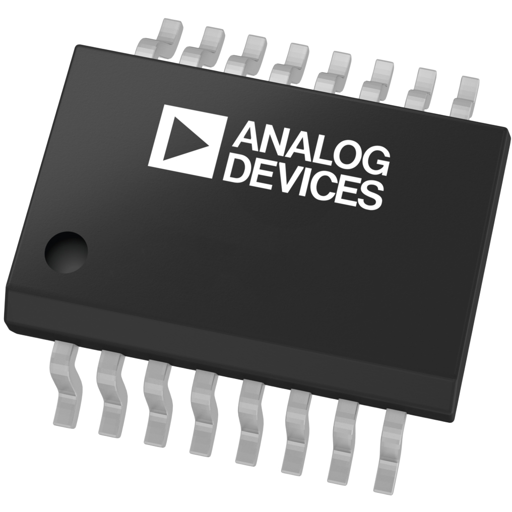
MAX1672EEE+T

ADIMAX1672EEE+T

Analog Devices Inc./Maxim Integrated
Buck, Boost Switching Regulator IC Positive Adjustable (Programmable) 1.25V (3.3V, 5.5V) 1 Output 300mA 16-SSOP (0.154", 3.90mm Width)
Active3,197 in stock

Overview

The MAX1672EEE+T is a high-efficiency buck-boost DC-DC converter capable of providing a steady 3.3V or 5.5V output from input voltages ranging from 1.8V to 11V. Unlike standard SEPIC or flyback converters, it utilizes a proprietary architecture that requires only a single small inductor to perform both step-up and step-down functions. This makes it an ideal solution for systems where the battery voltage starts above the target rail and eventually drops below it.

Why Choose This Part

The component features a very low 85uA quiescent current and a 0.1uA shutdown mode that completely disconnects the load from the input, preserving battery life. It eliminates the need for external FETs and uses a smaller inductor than traditional buck-boost topologies, saving significant board space. Built-in thermal and short-circuit protection ensure robust operation in compact portable designs.

Applications

Single-Cell Lithium Devices
Maintains a constant 3.3V output even as a Li-ion battery discharges from 4.2V down to its cutoff voltage.
Dual-Cell Alkaline Systems
Efficiently boosts voltage from 1.8V input sources to power 3.3V or 5V digital logic.
Portable Digital Cameras
Provides up to 300mA of current for image processors and peripherals while minimizing PCB footprint.
Battery Monitoring
Utilizes the integrated PGI/PGO low-battery comparator to provide early warning of power loss to the host MCU.

Key Specifications

Function Step-Up/Step-Down
Topology Buck, Boost
Output Type Adjustable (Programmable)
Mounting Type Surface Mount
Package / Case 16-SSOP (0.154", 3.90mm Width)
Current - Output 300mA
Number of Outputs 1
Output Configuration Positive
Operating Temperature -40degC ~ 85degC (TA)
Synchronous Rectifier No
Voltage - Input (Max) 11V
Voltage - Input (Min) 1.8V
Voltage - Output (Max) 5.5V
Supplier Device Package 16-QSOP
Voltage - Output (Min/Fixed) 1.25V (3.3V, 5.5V)

Getting Started

When designing the PCB, place the input and output filter capacitors as close as possible to the 16-QSOP package pins to minimize switching noise. Select a low-ESR inductor rated for at least 600mA to avoid saturation during peak switching cycles. Refer to the MAX1672 evaluation kit documentation for optimized layout patterns that manage thermal dissipation and ground loops.

Also Consider

MAX17222 Analog Devices - Suitable for ultra-low-power applications requiring higher efficiency at light loads with a much lower 300nA quiescent current.