






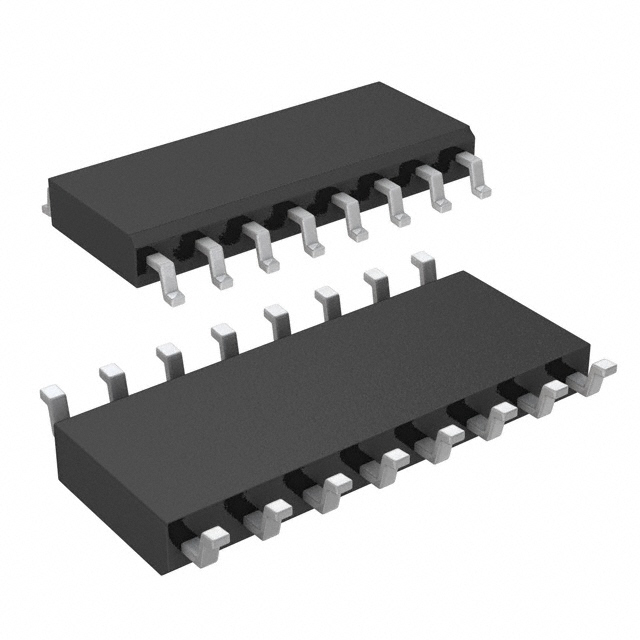
ADIMAX3045BESE+
Overview
The MAX3045BESE+ is a quad-channel RS-422/RS-485 line driver designed for high-speed digital data transmission up to 20Mbps. This 5V device integrates four independent drivers into a single 16-SOIC package, providing a space-efficient solution for multi-channel differential signaling. It features hot-swap capability to eliminate false transitions on the data bus during power-up or live insertion.
Why Choose This Part
It offers a high data rate of 20Mbps while maintaining low propagation delay and skew, which is critical for synchronous parallel data transmission. The quad-driver configuration reduces component count and PCB footprint compared to using multiple single or dual driver ICs. Additionally, its ESD protection and hot-swap circuitry ensure system reliability during maintenance and power cycling.
Applications
Key Specifications
Getting Started
Designers should place a 0.1uF ceramic bypass capacitor close to the VCC pin (4.75V to 5.25V) to manage switching transients. Ensure proper differential impedance matching on the PCB traces and use 120-ohm termination resistors at the receiver end of the transmission line. For evaluation, this part can be integrated into custom prototypes using a standard 16-pin SOIC to DIP adapter for breadboard testing.


