




EmbeddedRelated.com
Jacob Beningo
Live online course · Jacob Beningo
AI for Embedded Developers
$100 off for EmbeddedRelated readers until Dec 6 · 5 live sessions, Dec 7-11
Discount ends in
28days 02hrs 10min 34sec
Learn More →
TLVM365R15RDNR

TITLVM365R15RDNR

Texas Instruments
Non-Isolated PoL Module DC DC Converter 1 Output 3.3V 100mA 3V - 65V Input
Active3,750 in stock

Overview

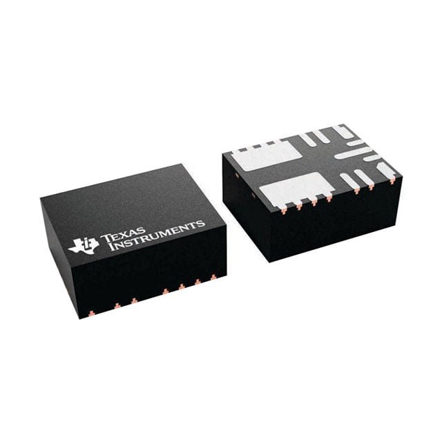
The TLVM365R15RDNR is a highly integrated, non-isolated power module designed for high-voltage input applications up to 65V. It combines a controller, MOSFETs, and the inductor into a compact 4.5mm x 3.5mm QFN package to simplify PCB layout and reduce electromagnetic interference.

Why Choose This Part

The module's main advantage is its extreme integration, which eliminates the need for external inductor selection and reduces the total bill of materials. It features a wide input range from 3V to 65V and an ultra-low shutdown current of approximately 0.55uA, making it ideal for power-sensitive designs.

Applications

High-Voltage Industrial Rails
Efficiently steps down 24V or 48V industrial bus voltages to 3.3V for low-power logic and sensors.
Field Instrumentation
Utilizes its small footprint and 4uA quiescent current for remote monitoring equipment with limited space.
Factory Automation
Serves as a reliable point-of-load regulator in systems requiring functional safety and robust thermal performance up to 125 degrees Celsius.

Key Specifications

Type Non-Isolated PoL Module
Features Adjustable Output, Remote On/Off
Applications ITE (Commercial)
Mounting Type Surface Mount, Wettable Flank
Package / Case 11-PowerFQFN Module
Size / Dimension 0.18" L x 0.14" W x 0.08" H (4.5mm x 3.5mm x 2.1mm)
Number of Outputs 1
Voltage - Output 1 3.3V
Operating Temperature -40degC ~ 125degC
Voltage - Input (Max) 65V
Voltage - Input (Min) 3V
Current - Output (Max) 100mA
Supplier Device Package 11-QFN-FCMOD (4.5x3.5)

Getting Started

Engineers can evaluate the design using the TLVM365R15EVM evaluation module and Texas Instruments WEBENCH Power Designer. When laying out the PCB, ensure the input and output capacitors are placed as close as possible to the module pins to minimize noise on the integrated inductor.