





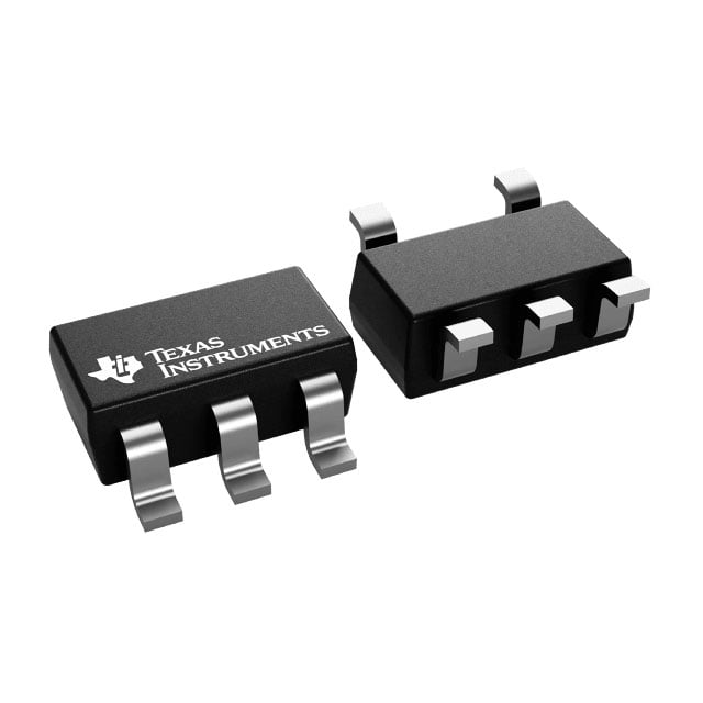
TITPS79328DBVRM3
Overview
The TPS79328DBVRM3 is a high power-supply rejection ratio (PSRR), low-noise, low-dropout (LDO) linear regulator from Texas Instruments. It provides a fixed 2.8V output from an input up to 5.5V, delivering up to 200mA of current. This device is specifically designed for noise-sensitive applications where a stable, clean power rail is required in a small SOT-23-5 footprint.
Why Choose This Part
This LDO features an exceptionally low-noise performance and high PSRR, making it ideal for RF and analog stages. It includes integrated protection such as under-voltage lockout (UVLO), reverse current protection, over-temperature shutdown, and over-current limiting. The small SOT-23 package and 250uA quiescent current provide a balance of thermal performance and power efficiency for space-constrained designs.
Applications
Key Specifications
Getting Started
To implement this part, place a high-quality ceramic bypass capacitor (typically 10nF) at the NR (noise reduction) pin and ensure input/output capacitors are placed as close to the device pins as possible. Use the Enable (EN) pin to toggle power for energy-saving states in battery-powered designs. Thermal relief patterns should be included in the PCB layout to manage heat dissipation at the maximum 200mA load.


