






Lost Secrets of the H-Bridge, Part III: Practical Issues of Inductor and Capacitor Ripple Current
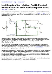
We've been analyzing the ripple current in an H-bridge, both in an inductive load and the DC link capacitor. Here's a really quick recap; if you want to get into more details, go back and read part I and part II until you've got equations coming...

Summary
This blog post analyzes practical ripple-current issues in H-bridge power stages, covering both inductive load ripple and DC‑link capacitor ripple. Readers will learn how ripple affects heating, capacitor lifetime, EMI, and how to size and choose inductors and capacitors for real motor-control applications.
Key Takeaways
- Calculate peak-to-peak inductor ripple from PWM parameters (voltage, duty cycle, inductance, switching frequency) to predict torque ripple and peak current.
- Estimate DC‑link capacitor ripple current and dissipation to size capacitors and prevent overheating or premature failure.
- Select capacitors based on ripple current rating, ESR, temperature derating, and expected lifetime rather than only capacitance value.
- Mitigate ripple and its side effects using higher switching frequency, snubbers/filters, layout improvements, and appropriate dead-time and control strategies.
Who Should Read This
Intermediate to advanced embedded and power electronics engineers (motor-control firmware/hardware designers) who need to size inductors and DC‑link capacitors and reduce EMI, heating, and lifetime issues in H-bridge designs.
TimelessAdvanced
Related Documents
- Consistent Overhead Byte Stuffing TimelessIntermediate
- PID Without a PhD TimelessIntermediate
- Introduction to Embedded Systems - A Cyber-Physical Systems Approach Still RelevantIntermediate
- Can an RTOS be really real-time? TimelessAdvanced
- Memory Mapped I/O in C TimelessIntermediate