EmbeddedRelated.com
The 2026 Embedded Online Conference

Digital PLL's -- Part 1

Neil Robertson
TimelessAdvanced

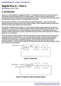
1. Introduction Figure 1.1 is a block diagram of a digital PLL (DPLL).  The purpose of the DPLL is to lock the phase of a numerically controlled oscillator (NCO) to a reference signal.  The loop includes a phase detector to compute ...


Summary

This article introduces the fundamentals of digital phase-locked loops (DPLLs), explaining the block diagram and the role of each element in locking a numerically controlled oscillator (NCO) to a reference. Readers will learn how phase detectors, loop filters, and NCOs interact and what design trade-offs matter when implementing a DPLL in embedded firmware.

Key Takeaways

  • Describe the main DPLL blocks and their functions (phase detector, loop filter, NCO)
  • Implement basic phase detector algorithms suitable for resource-constrained microcontrollers
  • Design a discrete-time loop filter and assess stability and bandwidth in the z-domain
  • Evaluate fixed-point vs floating-point choices and their impact on jitter and numerical behavior

Who Should Read This

Embedded firmware engineers or systems designers with an interest in implementing digital timing/control loops on microcontrollers who want practical guidance on DPLL building blocks and trade-offs.

TimelessAdvanced

Topics

Firmware DesignBare-Metal ProgrammingARM Cortex-M

Related Documents


The 2026 Embedded Online Conference