Voltage - A Close Look
My first boss liked to pose the following problem when interviewing a new engineer. “Imagine two boxes on a table one with a battery the other with a light. Assume there is no detectable voltage drop in the connecting leads and the leads cannot be broken. How would you determine which box has the light? Drilling a hole is not allowed.”
The answer is simple. You need a voltmeter to tell the electric field direction and a small compass to tell the magnetic field direction. From these directions, the right-hand rule indicates the energy flow direction.
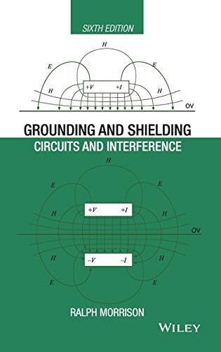
In writing my latest book titled Fast Circuit Boards – Energy Management, I had a need to review voltage and current patterns on transmission lines. I knew that as the initial wave moved down a transmission line, the leading edge of the wave stored energy in the line capacitance. When the forward wave reached the open circuit at the end of the line, the voltage doubled. I had assumed that energy for the voltage doubling was supplied by the reflected wave. What actually happens is the leading edge of the reflected wave converts the arriving forward magnetic field energy into electric field energy thus doubling the voltage. I realized that on a transmission line, it is incorrect to say that energy is reflected. I also realized it is incorrect to say that the reflected wave cancels the current at the open circuit. The problem is that this explanation implies losing energy which is not the case. There is no mechanism for losing energy on an ideal unterminated line.
It is interesting to follow the energy flow on a section of open transmission line. The voltage source supplies energy until the first reflected wave returns to the source. At this point in time, the voltage is doubled and the current is zero along the entire line. The second reflection at the voltage source converts half of the electric field energy into magnetic field energy. The current for this magnetic field does not come from the voltage source. It comes from the leading edge of the second reflected wave. The wave action of the leading edge converts half the electric field energy into magnetic field energy. Without energy losses, the voltage source supplies no more energy to the line. What I have described is the first part of a resonance. This should not be surprising as energy cannot leave the circuit unless there is heat or radiation. Also, energy cannot be put back into the power supply.
Electrical energy moves at the speed of light. The fields behind a wave front carrying energy are unmoving. In effect the fields provide a framework for energy motion. An analogy with a mechanical system may help. Consider the drive shaft in an automobile. The energy in motion depends on torque and rpm. The stress and rpm are static along the entire shaft length yet the shaft carries energy forward. The shaft is a framework that carries energy forward.
How does all this tie in with voltage? We measure voltage in fast circuits and we may not realize all the things that the voltage can represent. On a capacitance, it represents electric field energy storage. Across an inductance, it represents changing magnetic field energy and across a resistor it represents dissipation. On a transmission line, voltage is a measure of energy storage or flow or both. As we attempt to operate at faster and faster logic rates we need to keep an open mind as to what voltage may imply. I remind you that we rarely use ammeters, watt meters or field meters when we monitor signals on a circuit board. An oscilloscope is just a sophisticated voltmeter. If the mechanisms of energy motion are not understood, it is not possible to explain how a transmission line functions. Until someone invents an energy meter, voltage is the only observation tool we have.


- Comments
- Write a Comment Select to add a comment

I am a bit confused with the example of reading the voltage and field to determine battery and light locations.
There will be complimentary fields on both wires; the current flowing to the light must be returned to the battery. All I can say for sure is that the same current is passing through both wires.
The polarity tells us nothing. Given lossless wires I can't look for a drop pointing to the source.
If the source and load impedance are matched for optimum power transfer I should have the same heating in both the source and load boxes preventing temperature measurement to see which is hotter.
Check out Poynting vector.

My intent in writing this blog was to show that voltage alone does not show how energy is processed. I was surprised that nobody reacted to statements that voltage on a transmission line can represent energy storage or energy motion or both. Also my statement that energy is not reflected on a transmission line caused no reaction. Surely there must be questions.
I agree with bitking. Poynting vector as a representation of the energy field, as the author has expressed through the lack of an "energy meter", can't be directionally measured. But since we can pull volt meters and compasses from the ether why not just pull out an x-ray machine and be done with it. I believe the question of which box has the light in it is meant to test your problem solving ability and how well you communicate your way through it. Alternatively, if the boxes shared a common ground and a single wire transmission, then the volt meter and compass would be viable
Poynting vector is a "vector", which means that it measures directional energy flux. So it can indicate the direction of energy flow. That being said, there is an even easier way to solve this problem: find the most positive node (by using a voltmeter) and then measure the current of that node using a clamp meter, if the current is positive, the arrow on the clamp should point to the lamp.
Engxx, you don't need a clamp meter. In the problem you are given a compass and the right-hand rule. After locating the positive terminal/wire with the voltmeter, use them to find the current flow direction https://en.wikipedia.org/wiki/Right-hand_rule
piotrek, I agree, a compass is sufficient. The point is to find the current direction.
Engxx, you can use a compass to find the current direction.
https://www-istp.gsfc.nasa.gov/Education/whmfield.html
I appreciate the conceptual descriptions of what is happening on transmission lines. In a more conventional power system setting, the paradox I see is that as a load is added to a synchronous generator, the reflections from the mismatched impedance of the generator and load would cause an increase in voltage, which means you would want to reduce generator excitation. But in reality, the operator increases excitation because voltage drops when adding load.....I would be interested to understand how that works ....if someone could point me in the right direction...
Also, I was hoping Ralph would write something about the relationship between maximum power transfer and efficiency. Maybe point me in the right direction of an analogy. I would think the point of maximum power transfer, when source and load impedance match, is the point of maximum efficiency. Isn't that the time when all the energy passes through the load? In reality, maximum efficiency occurs when there is a mismatch of source and load impedance and there are reflections galore.....what's happening?
In circuit theory, the transfer of energy is optimized when the source impedance matches the termination impedance. This rule is not applicable to utility power where we expect a near zero source impedance. In logic designs where transmission lines interconnect components, the problem is to store or remove energy from the capacitance of transmission lines. It is impractical to terminate lines in their characteristic impedance as this consumes a great deal of energy. If a carrier is to be radiated, then matching to the impedance of free space becomes an issue.
To understand energy transfer at high frequencies, it is necessary to understand how nature functions. Nature pays no heed to our language or how we describe her activity. Nature has one goal and that is to take any action that will reduce the concentration of energy. This is why a dropped ball falls to earth or the sun heats the earth. In electricity, it is why a battery heats a resistor when placed across its terminals. All of this activity involves coupled electric and magnetic field energy.
We have invented circuit theory and a description of components that store energy so that we can do engineering and perform electrical tasks. It is too difficult to use the physics of electricity to design circuits. We often forget that the basis of our understanding is in physics. For example, voltage is really the work required to move a unit charge in an electric field between two points.
In moving charges into a capacitor, a magnetic field is involved. It turns out that every electrical activity requires both an electric and magnetic field. Both fields can store static energy. Moving energy involves both an electric and magnetic field acting together. The electric field is near zero in a metal which forces us to accept the idea that energy only moves in spaces not in conductors. The roll of conductors is to direct where energy flows and in circuits it is always in the spaces between conductors. This is also true in capacitors or inductors or between traces and ground planes.
Dear Ralph,
From my understanding, when a wave reflects, the Poynting vector reflects. Energy reflects back to the source. It is just like any wave that reflects from any surface. Both the E and H fields reflect.
It has been mathematically shown in books from Hall & Heck (Advanced signal integrity for high speed design) or by Paul Huray (foundations of signal integrity). Energy reflection can also be seen in 3D field solver viewers like Simbeor.
When you say that energy doesn't reflect back the wave reflects back, do you have any mathematical analysis that backs up the claim?
Thanks,
Binayak
To post reply to a comment, click on the 'reply' button attached to each comment. To post a new comment (not a reply to a comment) check out the 'Write a Comment' tab at the top of the comments.
Please login (on the right) if you already have an account on this platform.
Otherwise, please use this form to register (free) an join one of the largest online community for Electrical/Embedded/DSP/FPGA/ML engineers: