


Wye Delta Tee Pi: Observations on Three-Terminal Networks
Today I’m going to talk a little bit about three-terminal linear passive networks. These generally come in two flavors, wye and delta.
Why Wye?

The town of Why, Arizona has a strange name that comes from the shape of the original road junction of Arizona State Highways 85 and 86, which was shaped like the letter Y. This is no longer the case, because the state highway department reconfigured the intersection into a T-shaped connection; the town was not, however, renamed Tee. (To be pedantic about it, from a birds-eye view facing north, the intersection looks more like a Greek letter lambda \( \lambda \). Try selling that name to a small town.)

The wye configuration of a three-phase circuit gets its name for similar reasons, because wye-connected loads look like the letter Y in schematic form:
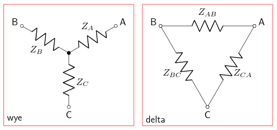
Another name for wye-connected loads is star-connected. The other common configuration is a delta-connected load. In a wye-connected load, each phase of the load connects from one of the phase terminals to the neutral terminal, for example \( Z_A, Z_B, Z_C \) in the diagram above. In a delta-connected load, each phase of the load connects between two adjacent phase terminals, for example \( Z_{AB}, Z_{BC}, Z_{CA} \) in the diagram above.
In some cases a wye-connected circuit may have its neutral terminal grounded. But in that case, we have three two-terminal circuits, which isn’t very interesting. Since this article is about three-terminal circuits, I’m going to talk only about wye-connected circuits with no additional connections to the neutral terminal.
Network Analysis Abstraction
One area of electrical engineering is network analysis — this is basically what all computerized simulation software uses to determine what’s going on in an electrical circuit. An important idea of network analysis is that you can consider any linear circuit network as a black box when viewed from its terminals. For the three-terminal circuit:
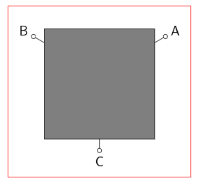
What can we say about this? There are three currents into the three terminals, \( I_A, I_B, I_C \), and three voltages \( V_A, V_B, V_C \). Assuming we don’t allow any unipolar charges to develop, we know \( I_A + I_B + I_C = 0. \) Also, we can use any of the terminals as a fixed voltage reference. This means for a linear circuit with no internal voltage / current sources,
$$\begin{bmatrix}V_{AC} \cr V_{BC}\end{bmatrix} = \begin{bmatrix}V_A - V_C \cr V_B - V_C\end{bmatrix} = \begin{bmatrix}Z_{11} & Z_{12} \cr Z_{21} & Z_{22}\end{bmatrix} \begin{bmatrix}I_A \cr I_B\end{bmatrix} $$
for some 2 × 2 matrix \( \mathbf{Z}. \) We don’t care whether it’s a wye or a delta circuit or something else; we can describe it completely by its externally-observable impedances. These may be a complicated function of frequency, but it’s still a 2 × 2 matrix.
It also means that if we have a wye circuit with some known values \( Z_A, Z_B, Z_C \), we can determine an equivalent delta circuit with values \( Z_{AB}, Z_{BC}, Z_{CA} \) and there’s no way to distinguish the two from their externally-measurable behavior.
Wye-Delta Transformation
There’s a fairly simple wye-delta transformation, shown by A. E. Kennelly in 1899 in Electrical World and Engineer.
We can derive it ourselves with a little bit of Grungy Algebra. For convenience I’m going to use single letters a through f as follows:
$$\begin{align} a&=Z_A \cr b&=Z_B \cr c&=Z_C \cr d&=Z_{AB} \cr e&=Z_{BC} \cr f&=Z_{CA} \end{align}$$
Suppose we leave terminal C open-circuited. Then the impedance between A and B is \( a+b \) for the wye and \( d\parallel (e+f) = \frac{de + df}{d+e+f} \) for the delta. These are equal if the circuits are equivalent. We can come up with similar equations for the other two cases of open circuits:
$$\begin{align} a+b&=\frac{de + df}{d+e+f} \cr b+c&=\frac{ef + ed}{d+e+f} \cr c+a&=\frac{fd + fe}{d+e+f} \end{align}$$
Add all three equations and divide by two and we get
$$a+b+c = \frac{de+df+ef}{d+e+f}$$
from which we can subtract each of the earlier equations and get
$$\begin{align} c&=\frac{ef}{d+e+f} \cr a&=\frac{df}{d+e+f} \cr b&=\frac{de}{d+e+f} \end{align}$$
This handles the conversion from delta to wye.
To go the other direction, from wye to delta, let’s short terminals A and B together and determine the impedance from these two terminals to C: \( (a \parallel b) + c = c + \frac{ab}{a+b} = e \parallel f = \frac{ef}{e+f} \). Write this as \( \frac{ab+ac+bc}{a+b} = \frac{ef}{e+f} \) and take reciprocals to get \( \frac{a+b}{ab+ac+bc} = \frac{e+f}{ef} \). We can get similar equations from the other two cases:
$$\begin{align} \frac{a+b}{ab+ca+bc} &= \frac{e+f}{ef} = \frac{de+df}{def}\cr \frac{b+c}{ab+ca+bc} &= \frac{f+d}{fd} = \frac{ef+ed}{def}\cr \frac{c+a}{ab+ca+bc} &= \frac{d+e}{de} = \frac{fd+fe}{def}\cr \end{align}$$
Add all three equations and divide by two to get
$$\frac{a+b+c}{ab+ca+bc} = \frac{de+ef+fd}{def}$$
from which we can subtract each of the earlier equations to get
$$\begin{align} \frac{c}{ab+ca+bc} &= \frac{ef}{def} = \frac{1}{d}\cr \frac{a}{ab+ca+bc} &= \frac{df}{def} = \frac{1}{e}\cr \frac{b}{ab+ca+bc} &= \frac{de}{def} = \frac{1}{f}\cr \end{align}$$
and take reciprocals to get
$$\begin{align} d &= \frac{ab+ca+bc}{c} = a + b + \frac{ab}{c}\cr e &= \frac{ab+ca+bc}{a} = b + c + \frac{bc}{a}\cr f &= \frac{ab+ca+bc}{b} = c + a + \frac{ca}{b}\cr \end{align}$$
In terms of the original impedances in the wye and delta diagrams, we have the delta to wye conversion:
$$\begin{align} Z_A&=\frac{Z_{AB}Z_{CA}}{Z_{AB}+Z_{BC}+Z_{CA}} \cr Z_B&=\frac{Z_{AB}Z_{BC}}{Z_{AB}+Z_{BC}+Z_{CA}} \cr Z_C&=\frac{Z_{BC}Z_{CA}}{Z_{AB}+Z_{BC}+Z_{CA}} \end{align}$$
and the wye to delta conversion:
$$\begin{align} Z_{AB}&=Z_A + Z_B + \frac{Z_AZ_B}{Z_C} \cr Z_{BC}&=Z_B + Z_C + \frac{Z_BZ_C}{Z_A} \cr Z_{CA}&=Z_C + Z_A + \frac{Z_CZ_A}{Z_B} \cr \end{align}$$
Examples
Example 1: Balanced Impedances
In the case where \( Z_A = Z_B = Z_C = Z_Y \), we have \( Z_{AB} = Z_{BC} = Z_{CA} = Z_\Delta = Z_Y + Z_Y + {Z_Y}^2/Z_Y = 3Z_Y \).
To go from wye to delta, multiply the impedances by 3. To go from delta to wye, divide the impedances by 3.
Power engineers like balanced three-phase loads. They’re very nice and simple and beautiful.
Example 2: Two Almost-equal Impedances and a Third Larger Impedance
Suppose we have \( Z_A = 10K\Omega(1 + \varepsilon) \), \( Z_B = 10K\Omega(1 - \varepsilon) \), \( Z_C = 1M\Omega \) for a wye circuit. (The \( \varepsilon \) represents ratiometric error.)
Then the equivalent delta circuit with values, in ohms, is
$$\begin{align} Z_{AB} &= 20K + 100(1 - \varepsilon^2) = 20.1K - 100\varepsilon^2\cr Z_{BC} &= 1.01M - 10K\varepsilon + 1M(1 - \varepsilon)/(1+\varepsilon) \approx 2.01M - 1M(2.01\varepsilon) = 2.01M(1-\varepsilon)\cr Z_{CA} &= 1.01M + 10K\varepsilon + 1M(1 + \varepsilon)/(1-\varepsilon) \approx 2.01M + 1M(2.01\varepsilon) = 2.01M(1+\varepsilon) \cr \end{align}$$
where the ≈ comes from the fact that \( (1-\varepsilon)/(1+\varepsilon) \approx 1-2\varepsilon \) for \( |\varepsilon| \ll 1 \).
This case (the “approximately isosceles” case if you envision the delta case as a triangle with side lengths proportional to impedance) is interesting in a couple of ways:
- The ratio between resistors in the wye case is approximately 100:1, and in the delta case it is also approximately 100:1
- The ratiometric imbalance is maintained almost exactly: it affects the two almost-equal values in the same way, and it barely affects the third value at all. (If \( \varepsilon = 0.1 \) or 10%, which is fairly large, since you can buy cheap 1% resistors, then we have \( Z_{AB} = 20.101K\Omega \) instead of \( 20.1K\Omega \).)
- The ratio between resistances is very close to 2:1; in general, if \( Z_A = Z_B = kZ_C \) then \( Z_{AB} = 2Z_A + {Z_A}^2/(Z_A/k) = (2 + k)Z_A \), and \( Z_{BC} = Z_{CA} = Z_C + kZ_C + Z_C = (2+k)Z_C \). This case involves \( k \ll 1 \), in this example \( k=0.01. \)
Example 3: Two Almost-equal Impedances and a Third Smaller Impedance
This is a similar case but with \( k \gg 1 \); if the two impedances \( Z_A \) and \( Z_B \) are exactly equal then we still have \( Z_{AB} = (2+k)Z_A \) and \( Z_{BC} = Z_{CA} = (2+k)Z_C \), as in the previous example.
Suppose we have \( Z_A = 10K\Omega(1 + \varepsilon) \), \( Z_B = 10K\Omega(1 - \varepsilon) \), \( Z_C = 100\Omega \) for a wye circuit.
Then the equivalent delta circuit with values, in ohms, is
$$\begin{align} Z_{AB} &= 20K + 1M(1 - \varepsilon^2) = 1.02M - 1M\varepsilon^2\cr Z_{BC} &= 10.1K - 10K\varepsilon + 100(1 - \varepsilon)/(1+\varepsilon) \approx 10.2K - 10K(1.02\varepsilon) = 10.2K(1-\varepsilon)\cr Z_{CA} &= 10.1K + 10K\varepsilon + 100(1 + \varepsilon)/(1-\varepsilon) \approx 10.2K + 10K(1.02\varepsilon) = 10.2K(1+\varepsilon)\cr \end{align}$$
Note that
- The ratio between resistors in the wye case is approximately 100:1, and in the delta case it is also approximately 100:1
- The ratiometric imbalance is maintained almost exactly: it affects the two almost-equal values in the same way, and it barely affects the third value at all for small \( \varepsilon \), although not as small as in the previous case. (If \( \varepsilon = 0.1 \) or 10%, which is fairly large, since you can buy cheap 1% resistors, then we have \( Z_{AB} = 1.01M\Omega \) instead of \( 1.02M\Omega \).)
- The two almost-equal resistances don’t change much (\( Z_A \approx A_B \approx Z_{BC} \approx Z_{CA} \)). More accurately they change by a factor of approximately \( 1+\frac{2}{k} \).
- The odd resistance changes from being smaller by a factor of \( k \) in the wye configuration, to larger by a factor of \( k \) in the delta configuration.
Example 4: Three Unequal Impedances
Suppose we have \( Z_A = 1\Omega \), \( Z_B = 2\Omega \), \( Z_C = 5\Omega \) for a wye circuit.
These equations tell us that the equivalent delta circuit impedances, in ohms, are
$$\begin{align} Z_{AB} &= 1 + 2 + 2/5 = 3.4\cr Z_{BC} &= 2 + 5 + 10 = 17 \cr Z_{CA} &= 5 + 1 + 5/2 = 8.5 \end{align}$$
And going the other way, we have
$$\begin{align} Z_A &= \frac{3.4\cdot 8.5}{3.4+17+8.5} = \frac{28.9}{28.9} = 1\cr Z_B &= \frac{3.4\cdot 17}{3.4+17+8.5} = \frac{57.8}{28.9} = 2\cr Z_C &= \frac{17\cdot 8.5}{3.4+17+8.5} = \frac{144.5}{28.9} = 5\cr \end{align}$$
Tee and Pi Networks
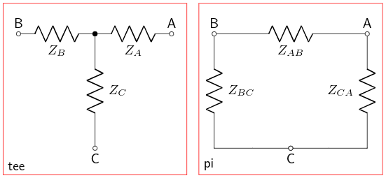
If we connect one of the terminals (for example, terminal C) to a circuit ground, then these are traditionally drawn orthogonally rather than at 120° angles, and the wye and delta configurations are known as T (or tee) and π (pi) networks:
The black-box equivalent is a two-port network. Now, technically a two-port network has no common voltage (each port could be galvanically isolated from the other), but in many circuits the negative-side terminals are common. Let’s label the voltages and currents:
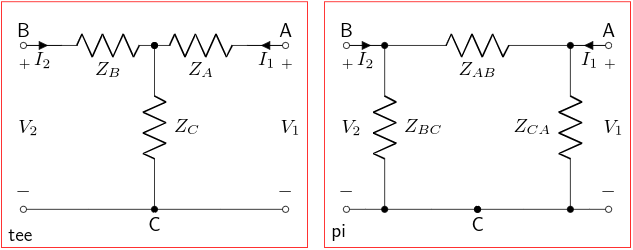
The tee network is easy to specify as impedances \( \mathbf{V}=\mathbf{Z}\mathbf{I} \); we can read them off by using superposition (first imagine \( I_2 = 0 \) and calculate voltages \( V_1 \) and \( V_2 \) from \( I_1 \); then do the same with \( I_1 = 0 \))
$$\begin{bmatrix}V_{1} \cr V_{2}\end{bmatrix} = \begin{bmatrix}Z_{11} & Z_{12} \cr Z_{21} & Z_{22}\end{bmatrix} \begin{bmatrix}I_1 \cr I_2\end{bmatrix} = \begin{bmatrix}Z_A+Z_C & Z_C \cr Z_C & Z_B+Z_C\end{bmatrix} \begin{bmatrix}I_1 \cr I_2\end{bmatrix} $$
whereas the pi network is easy to specify as admittances \( \mathbf{I}=\mathbf{Y}\mathbf{V} \)
$$\begin{bmatrix}I_{1} \cr I_{2}\end{bmatrix} = \begin{bmatrix}Y_{11} & Y_{12} \cr Y_{21} & Y_{22}\end{bmatrix} \begin{bmatrix}V_1 \cr V_2\end{bmatrix} = \begin{bmatrix}1/Z_{CA} + 1/Z_{AB} & -1/Z_{AB} \cr -1/Z_{AB} & 1/Z_{BC} + 1/Z_{AB}\end{bmatrix} \begin{bmatrix}V_1 \cr V_2\end{bmatrix} $$
and presumably, if you’re willing to go through the Grungy Algebra, multiplying the two matrices \( \mathbf{Y}\mathbf{Z} \) will give you the identity matrix.
We can spot-check this for the impedances in Example 4:
import numpy as np

Za = 1.0
Zb = 2.0
Zc = 5.0
Zab = 3.4
Zbc = 17.0
Zca = 8.5

Z = np.matrix([[Za+Zc, Zc],[Zc, Zb+Zc]])
Y = np.matrix([[1/Zca+1/Zab, -1/Zab],[-1/Zab, 1/Zbc+1/Zab]])

print("Y=%s\nZ=%s" % (Y,Z))
Y=[[ 0.41176471 -0.29411765]
 [-0.29411765  0.35294118]]
Z=[[ 6.  5.]
 [ 5.  7.]]
Y*Z
matrix([[  1.00000000e+00,  -4.44089210e-16],
        [  2.22044605e-16,   1.00000000e+00]])
Well, close enough, anyway.
Notice that the \( \mathbf{Y} \) and \( \mathbf{Z} \) matrices are symmetric. Those of you who are linear algebra fanboys have got your ears perked up and may be salivating, wondering, “Is it positive definite? Is it positive definite?” We can check:
$$\begin{align}\mathbf{v}^\mathbf{T}\mathbf{Z}\mathbf{v} &= \begin{bmatrix}u & v\end{bmatrix}\begin{bmatrix}Z_A+Z_C & Z_C \cr Z_C & Z_B+Z_C\end{bmatrix} \begin{bmatrix}u \cr v\end{bmatrix} \cr &= \begin{bmatrix}u & v\end{bmatrix}\begin{bmatrix}Z_Au+Z_Cu+Z_Cv \cr Z_Cu+Z_Bv+Z_Cv\end{bmatrix}\cr &= Z_Au^2+Z_Cu^2+Z_Cuv + Z_Cuv+Z_Bv^2+Z_Cv^2 \cr &= Z_Au^2+Z_C(u^2+2uv+v^2)+Z_Bv^2 \cr &= Z_Au^2+Z_C(u+v)^2+Z_Bv^2 \ge 0 \end{align}$$
so, yes, \( \mathbf{Z} \) is positive semidefinite as long as the impedances \( Z_A, Z_B, Z_C \) are not negative, and strictly positive definite if at least two of the impedances \( Z_A, Z_B, Z_C \) are positive.
This means that \( \mathbf{Y}=\mathbf{Z}^{-1} \) is also positive semidefinite or positive definite.
Maybe one of the linear algebra fanboys can tell me what this actually means in terms of circuit behavior. Probably something to do with the fact that the energy dissipated in these impedances is always nonnegative or positive.
Applications
Okay, enough of the algebra. These wye, delta, tee, and pi networks and their transformations have real applications in circuit analysis and synthesis. The analysis applications are straightforward; you can swap between wye/delta or tee/pi equivalents whenever it makes it easier to analyze a particular circuit. As far as synthesis goes, sometimes one of the equivalents is easier to utilize than the other. Here’s one example:
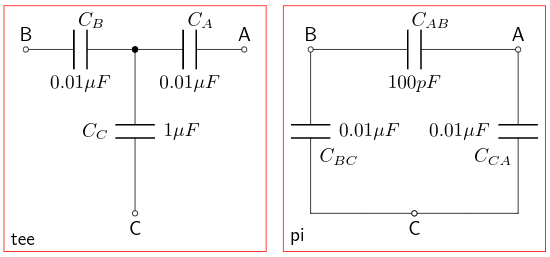
Let’s say you want to make a tee circuit with capacitors \( C_A = C_B = 0.01\mu F \) and \( C_C = 1\mu F \), but the \( 1\mu F \) capacitors are out of stock, or they’re too expensive, or you can’t get them in NP0/C0G grades for temperature stability. These have the same ratios as in our Example 3 (remember, \( Z=1/j\omega C \) for a capacitor so \( C_C \) has the lowest impedance) so they can be transformed to \( C_{AB} \approx 0.0001\mu F / 1.02 = 100pF / 1.02 \) and \( C_{BC} = C_{CA} \approx 0.01\mu F / 1.02 \) and we can drop the 1.02 factor (close enough!) to get \( C_{AB} = 100pF \) and \( C_{BC} = C_{CA} = 0.01\mu F \). We’ve swapped out a 1μF capacitor for a 100pF capacitor; these are cheap and easily available in NP0/C0G grades.
I’m sure there are some other applications to discuss, such as the Twin-T notch filter, but none of them are familiar enough to me to discuss here.
Wrapup
We talked about wye, delta, tee, and pi circuits including:
- the equivalent impedance transformations
- several specific cases such as two impedances almost equal and the third somewhat different
- the network impedance matrix representation
© 2018 Jason M. Sachs, all rights reserved.


- Comments
- Write a Comment Select to add a comment
To post reply to a comment, click on the 'reply' button attached to each comment. To post a new comment (not a reply to a comment) check out the 'Write a Comment' tab at the top of the comments.
Please login (on the right) if you already have an account on this platform.
Otherwise, please use this form to register (free) an join one of the largest online community for Electrical/Embedded/DSP/FPGA/ML engineers:


