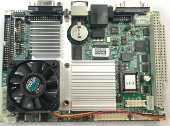
Anybody experienced in Advantech PCM 9373
I picked a couple out of the 'for later use' pile. They each came with Philips LP104S5 LCD panels/.
I want to build a dual dhcp and nfs server and thought that they would be ideal to use. They have 1GHz processors.
Can't get into CMOS setup, or any display for that matter, on either VGA output or LCD panel. Computer beeps when LCD panel not connected, so it is recognising it. Tried with both 128MB and 512 MB PC-133 memory.
Also, there is no HV DC to drive the backlight CCFD. Input pins has 12V, 1.4V and GND.
Problem is inconsistency between v1 manual and hardware, no later rev on Advantech site. It says VGA connector is a 16-pin header, but there is a DE15 connector. Also says CMOS battery is internal to the chip but has socket for CR1632, which I replaced with a new cell after discharging, still no output. . The BIOS eeprom says V1.16
Anybody know anything to with try with it? Their web site has a link to RedHat install procedure, so I know I can use it once I get past this point!
Thanks for any help,
Nigel

Hi,
while not having experience with this specific board ... 15 pin is the normal pin-out of VGA, so, did you connect a VGA monitor to the DE15 connector? You should see if the BIOS comes up.
Does the beepcode change, if you remove the DRAM?
After all, are these boards knowingly ok? Or sold for parts?
Thanks for the reply. If I remove he dram, the beep changes, I think it is double that of when I remove the LCD panel. Yes, I did connect a VGA monitor to the DE15. I'm pretty sure they were sold as working pulls, many years ago. The complete system was sold, including mag stripe scanners, fingerprint scanners etc as if some equipment was scrapped after working. I had one of them working decoding packets on a ham radio data channel up in the boiler room of my condo where I live, but took it down a few years back and replaced it with a raspberry pi! The manual says that the CMOS battery is integral, and that when it fails the whole unit has to be replaced, but it has a button cell so I am thinking that the manual I have is an old rev. But even if the CMOS was dead I should see some video!

Don't rely to much on "replace the complete unit", chinese documentation often has to be interpreted.
I suppose you already have reset the BIOS config? S2 seems to be a pushbutton instead of a jumper, somewhat hidden by the heatsink -- see picture and PDF attached.

Advantech_PCM9373_Overview.pdf
Other way: as the LCD seems to be recognised, you maybe have a screen but cannot see it because of the missing backlight. So, try to get the backlight run. Or use a torch to light the display from the side, so you can see if there is any meaningful display (some shadows should be seen).
If all that fails, I am running out of ideas.
Thanks for that. Yes, the documentation seems to be out of rev with the board. I have tried lighting it from behind with a torch (when I came here I had to learn to say 'flashlight' - never figured why these NA types say that when it doesn't flash ) I am never sure if I have push that little push-button under the heat sink! Maybe I will try peeking under there with a boroscope! The only thing is that where the the pushbutton would be, there is something that looks gold but the reset pushbutton has a silver enclosure.
As far as having a screen goes, I scoped the connector but cannot see any activity! I have tried all sixteen combinations of the option switch!
By the fact that you have a picture, have you got one running?

1) As my mother tongue is German, I don't care about UK/US nomenclature ... ;)
2) The color/colour of the pushbutton is of no importance. Maybe because the reset pushbutton is SPST and the reset BIOS pushbutton is SPDT.
2) No, I don't have one of these, the picture is the result of my preferred search engine.
3) Did you noted the original setting of the switches?
That's it for now ... my timezone is UTC+2.
Thanks for your suggestions, have a good sleep :-)


