


UART communication with ACK/NACK error handling
SETUP: Since there is a bit of complexity to the program, I made flowchart for each transmitter and receiver (only main aspects of code considered).
Transmitter&Receiver Flowchart-min-min.jpg
Here is code for transmitter (PIC18F46K80). Code for receiver is not same, but is similar to this one. Also, I use LEDs to indicate current position of program execution (e.g. when program is looping through "error" path or when is looping through "normal operation" path) and received data interpretation (LED bar graph connected in parallel to PORTD) but this is not included here (to improve code readability):
#include <xc.h>
#include <stdint.h>
#include <stdbool.h>
#include "config_bits_K80.h"

void osc_initialize(void);
void uart_initialize(void);
void uart_receive(uint8_t *c);
void uart_transmit(uint8_t *c);
void __interrupt() high_isr(void);

uint8_t data_rec;     // received data storage variable
uint8_t isr_flag = 0; // used to indicate completion of ISR
uint8_t ack = 0x06;   // acknowledgement code
uint8_t nack = 0x15;  // negative acknowledgement code


// INTIALIZE INTERNAL OSCILLATOR REGISTERS
void osc_initialize(void){
    OSCCONbits.SCS = 0b10;         // set internal oscillator block
    OSCCONbits.IRCF = 0b101;       // set clock frequency to 4MHz
    while(OSCCONbits.HFIOFS == 0); // wait for oscillator frequency to stabilize
}

// INITIALIZE UART REGISTERS
void uart_initialize(void){
    // RX and TX inputs port initialization
    TRISDbits.TRISD6 = 1;
    TRISDbits.TRISD7 = 1;

    SPBRG2 = 25;          // SPBRG = ((F_osc/BaudRate)/64)-1 => at F_osc = 4MHz, BaudRate = 2400, low speed
    TXSTA2bits.BRGH = 0;  // 8-bit data mode setting for transmitter/receiver
    TXSTA2bits.SYNC = 0;  // asynchronous mode
    RCSTA2bits.SPEN = 1;  // RX and TX set as serial port pins
    TXSTA2bits.TXEN = 1;  // transmitter enable
    RCSTA2bits.CREN = 1;  // receiver enable

    INTCONbits.GIEH = 1;  // must be set for HP interrupt to be generated
    INTCONbits.GIEL = 1;  // must be set for LP interrupt to be generated
    PIE3bits.RC2IE = 1;   // enable USART receive interrupt
}

// UART TRANSMISSION FUNCTION
void uart_transmit(uint8_t *tran){
    do{
        TXREG2 = *tran;              // load the value of "tran" into TXREG (data stored into TXREG, then send into TSR)
        while(TXSTAbits.TRMT == 0);  // wait for data to be loaded into TSR and send
        while(isr_flag == 0);        // loop is terminated after ISR
        isr_flag = 0;                // reset "isr_flag"
    } while(data_rec != ack);        // got NACK (or anything else) -> re-transmit current data
}


// UART RECEPTION FUNCTION
void uart_receive(uint8_t *rec){

    // MAIN ERROR - overrun
    if(RCSTA2bits.OERR){
        RCSTA2bits.CREN = 0;  // to clear error, reception module must be reset
        RCSTA2bits.CREN = 1;
        RCREG2;               // dummy read - part of module reset
        RCREG2;               // dummy read

        *rec = nack;          // current setting: if(OERR); discard data and re-transimission
    }
    // MINOR ERROR - framing
    else if(RCSTA2bits.FERR){
        RCREG2;      // dummy read - part of module reset

        *rec = nack; // current setting: if(FERR); discard data and re-transmission
    }
    // NORMAL OPERATION
    else{
        *rec = RCREG2; // store received data to "rec"
    }
}

// ISR WHEN REQUEST FOR RECEPTION HAPPENS
void __interrupt() high_isr(void){
    INTCONbits.GIEH = 0;
    // when interrupt for receptions occurs
    if(PIR3bits.RC2IF){
        uart_receive(&data_rec);
        isr_flag = 1;
    }
    INTCONbits.GIEH = 1;
}

void main(void) {

TRISC = 0;
TRISD = 0;
LATC = 0;
LATD = 0;

osc_initialize();
uart_initialize();

uint8_t data_tran[] = {"ABCDE"};   //character set to be transmitted

while(1){
    for(int i = 0; data_tran; i++){
        // GENERATE DELAY WHILE CONTINUOUSLY CALL TRANSMISSION
        for(float j = 0; j < 5; j += 0.1){
            uart_transmit(&data_tran);
        }
    }
}

return;
}
CODE EXPLANATION: From main(), I'm calling for uart_transmit() function, which transmits one character at the time (and generating sufficient delay, so I can observe transmitted data on LED bar graph (serially received data is outputted in parallel to PORTD)). After character is send, transmitter simply waits for transmission of ACK or NACK from receiver - if it gets ACK, transmit next character; if it gets NACK, re-transmit current character until it gets ACK.
As for receiver, it waits in main() (in loop) for ISR request. After data is loaded into RSR register, uart_read() function is performed. If data is received without any error, data is outputted on PORTD, ACK is sent to transmitter and program returns to main(). If there is an error regarding reception of character, data on PORTD remains unchanged (bad data is discarded), NACK is sent to transmitter and program returns to main(), where it waits for re-transmission of character.
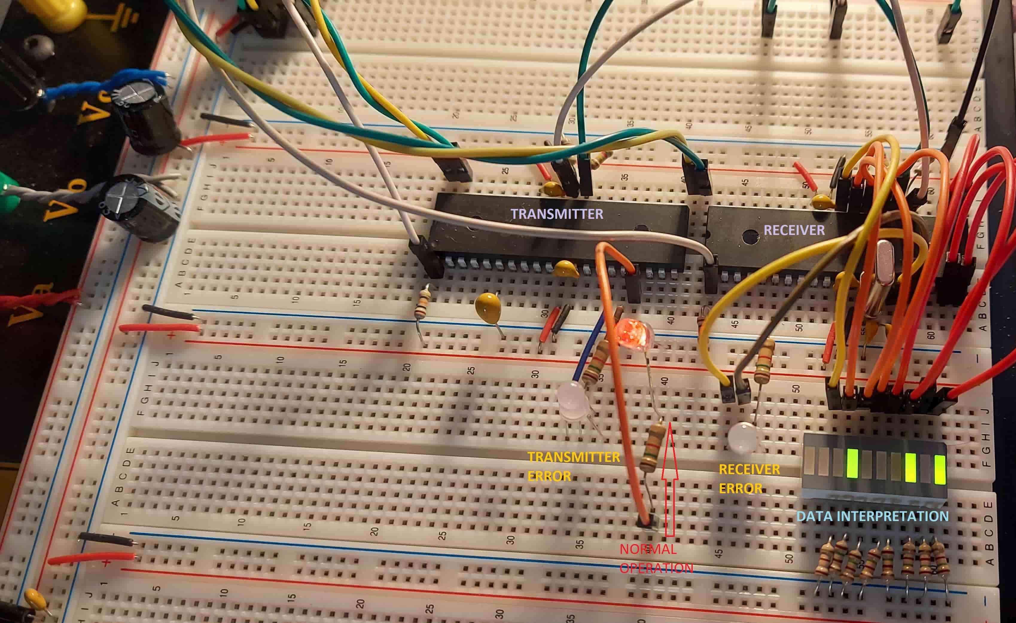
REAL LIFE IMPLEMENTATION: First of all, program won't even start correctly, if both TX and RX lines (on both sides of devices) aren't slightly loaded (added 1M Ohm resistor to GND at both pins at both sides). Otherwise, program works as intended, if there is no special event, like disconnecting either of data lines (and triggering either of FERR for transmitter or receiver - to simulate error handling). If that happens, LED indicates that program is looping through "error" path but as I connect back unconnected line, path returns to "normal operation" only from time to time (which is the strangest fact). Also, resetting both devices simultaneously also works from time to time.
CONCLUSION (to the problem): I suspect there is some issue regarding timing, when error is (or should be) reset and program is (or should be) returning to "normal operation" path. However, I cannot grasp, what timing error am I missing here.
After character is transmitted, F452 waits until TSR is empty (even if there is no need for that here, since it waits for ACK/NACK). After character is received by F452, uart_receive() is called only after RSR is full and when ACK/NACK is transmitted, uart_transmit() is ended immediately - not waiting for TMRT to be set - because program need to be back to uart_receive() then back to ISR then back to main() BEFORE new interrupt happens due to re-transmission from 46K80.
Considering all that timing facts, I really cannot solve this issue further on by myself.
EDIT: I realized that pull-up resistors are needed for UART to operate properly (RX not picking up noise), but after re-wiring, now the program won't even start executing; that is, data won't start transmitting and also I get no indication of any error.
Another fact is that when it works (if no resistor is used), data should be transmitted from transmitter also in case if any data line is disconnected; that is, if any error triggers. But it isn't transmitted - as soon as any error shows up, TX line (of transmitter) goes high.
I'd stablish 3 words of control. Keep alive control, word of reception control and broken chanel word control.
Betwen 2 keep alives the train of words ...in reception word with 1 o 0 depending word ok or bad in the train of transmisión.
Whith the channel broken in tx ...word from channel broken in reception
Cheers
Can you elaborate slightly more on what "keep alive" and "broken channel" word of control mean?
I think I understand what "word of reception" control means - just like "ACK" but instead transmitter gets "1" from receiver and just like "NACK" it gets "0" from receiver, right?
Also, if someone knows any good sources regarding UART error handling in embedded systems, I would gladly get into that.
Between k.a and k.a you send for example 8 words. If the reception goes well you'll receive 11111111 between two k.a.. If anyone fault 11011110 un a word (one byte). For to resend.3 and 8
You can complicate the transmition a much as you want.
Crc.. etc etc etc

I did not read all and everything ...
1) Declare all vars modified in ISR as volatile, so the compiler is forced to re-read them. Otherwhise re-reading may be omitted by optimization!
2) Using a float in a for() loop is never a good idea!
3) This seems to be wrong:
// UART TRANSMISSION FUNCTION
void uart_transmit(uint8_t *tran){
    do{
        if(data_rec != ack) LATCbits.LATC2 = 0; // indication (red LED)
        TXREG2 = *tran;                 // load the value of "tran" into TXREG (data stored into TXREG, then send into TSR)
        while(TXSTAbits.TRMT == 0);     // wait for data to be loaded into TSR and send
        while(isr_flag == 0);           // loop is terminated after ISR
        isr_flag = 0;                   // reset "isr_flag"
    } while(data_rec != ack);           // got NACK (or anything else) -> re-transmit current data
}
After the current byte is sent, you have to wait a full byte length for the ACK/NACK reply! But you immediately begin to retransmit. Also keep in mind: - breadboards do not have reliables contacts, - the clocks of the two PIC are RC oscillator and may differ quite a lot if not calibrated at startup (at least this the case for the small PIC12/PIC14 devices).
Forgotten:
- sending an ACK/NACK after each byte is to much and slows down the communication to half the baud rate. Also sending a NACK is not necessary. Just send an ACK after a few bytes transmitted. The TX only listen to ACK within a timeout and begin (limited) retransmits if no ACK has been received. If all retransmits fails the communication is broken.
- looking closer to the breadboard: one PIC seems to be XTAL driven, the other RC oscillator. Both clocks should not differ more than 5%! Otherwhise you get communication errors. Assume 8N1, then you transmit 10 bits in total. At RX, each bit is sampled within the middle of its transmitting time, here the 5% tolerance max! Better both clocks are exactly the same.
Regarding volatile, I will try and understand why is needed there and use it properly, then.
float is only for generation of delay in main() (so characters of data are being sent with considerable delay so I can observe data transmission on oscilloscope and LED indicators). Otherwise I know that float considerably slows down entire operation.
Regarding the code you replied with: after I'm calling TXREG2 = *tran program waits in the loop while(TXSTAbits.TRMT == 0) - it waits for TSR register to transmit the data and after that TRMT = 1. After that it waits in while(isr_flag == 0) until ISR is called (that is when it receives RCIF or interrupt for reception from receiver). From ISR, the uart_receive() is called (receives ACK/NACK), returns to ISR and only then it re-transmits same byte of data (if error occurred or got NACK).
As you can see, re-transmission is not immediate; unless I'm missing something.
Regarding clock sources I agree with you. I will try to derive clock pulse from same (stable) XTAL to reduce possibilities of unpredicted operation.
Regarding speed of transmission: for now I'm only seeking to establish "firm", stable and relatively safe communication path with proper error checking (and later on data verification algorithms, like checksum, CRC, etc.). I am not worried with efficiency of transmission just yet. That is to be accounted for after I grasp and fully understand the basics.
*P.S.: I edited code readability now, so now should be easier understandable regarding each section.
Ok, I missunderstood the function. But waiting forever on an answer is no good idea. If the link is broken this is a deadlock. You should work with timeouts.
And, ACKing each byte is useless, it does NOT secure the transmission. If a data bit is corrupted cannot be detected like this. Better send telegrams, secured with CRC. All ok on RX: send ACK. Otherwhise NACK. TX must also wait for timeout if RX is dead.
Okay, I agree with you, but this is early version of this program - for start I was only trying to realize some basic error checking (I read somewhere about ACK/NACK principle and I tried it). I completely realize that this program isn't validating data in any way (which is what CRC or checksum does).
I tried to go with ACKing every single byte of transmitted data only for start. I know is impractical since it "takes" too much speed from transmission for given baud rate. But still, is there any other reason that ACKing for every single byte won't work (other than speed)? "send byte -> get ACK -> send new byte" OR "send byte -> get NACK -> re-sent same byte -> get ACK -> send new byte" This principle should work, right? Or is something greatly wrong with it (not considering speed and efficiency)?
For starters, I just want to make the circuit operation and then move to efficiency but it looks like I cannot get it working properly - first proper operation, then improve efficiency.
Again, this does not work if the RX is dead, missing etc. In this case you must use a timeout or your system hangs forever.
For now, I only have to find what is the main problem here; why isn't the program responding as programmed. After I find, where is the catch, I can then move on to improving my "inefficient" design.
So, if you (or anyone else) have any doubts regarding code, I would gladly listen, because I checked every section 10x times, at lest, but could still say, it should operate. However, it doesn't.
When solving this problem I can, at least, start searching for bug from the fact that this program works, if no error checking is implemented (if error, discard data and ignore).
First, check the clocks! They don't need to be exactly the same, but as said not more than 5% different. For example, if the TX is to slow, the RX will sample a data bit as stop bit, which (depending on data, of course) can cause an error.
If you do not fix the basics it is useless to go further ...
Wondering about the pullup/pulldown-story, in the first post ... UART lines are active driven, i.e. totem-pole. Contrary to open-drain I2C.
This on the TX MCU side:
    TRISDbits.TRISD6 = 1;
    TRISDbits.TRISD7 = 1;
is wrong, as TRISD6 must be 0 (TX = output). And of course the same on the other side, the RX MCU.
Also the RX/TX lines between both MCUs must be crossed:
RX <----> TX
TX <----> RX
Then no pullups/pulldowns are necessary.
Well, that is obviously a mistake. Thanks for reminder!
Why do you think pull-up is not required? Might be useful in case of microprocessor reset (or programming) so the RX pins on both sides don't pick up any noise (and don't float) until they are initialized as inputs.
If both MCU are hardwired you don't need pullups. After booting you must anyway clear all receiver buffers.
Pullups should be used if the RX line can be left open.
But, if you use real RS232 drivers and receivers the RX line is high when nothing is connected on the RS232 side, so again no pullup required.
One reason for choosing pull-ups is that I chose to simulate framing error with breaking physical connection of transmission line from transmitter to receiver. However this might not be the best way to do so. Maybe I could just quickly connect TX line to GND (during transmission) to observe how both devices respond to that with error handling but again, this might not be the best idea.
Otherwise I cannot recall of any way to simulate error and still get visible results (not in range of microseconds, since that cannot be spotted, really).
If the TX pin is configured as (totem-pole) output, as it should be, it is not a good idea to directly shorten that pin to GND or Vdd!
You can however put a, say 1k, resistor in series in the TX line and shorten behind the resistor, on the receiver side. This reduces the current out of the TX pin.
Sorry, this is basic electronic knowledge, is this your first design?
No, its not first design, but I'n not "native" in these waters just yet either. I know shorting output directly to either of power supply pins is stupid and can be destructful for microcontroller, but I just couldn't figure out and better way to simulate error (not on data).
Ok, don't mind, meanwhile I saw your profile. Although most MCU will not be destroyed immediately by a short an outputs it is strongly deprecated to do this. Use a series resistor and everything is fine.
Keep in mind that a mechanical switch (or short by hand) produces a lot of bounces. Say to increment a counter this is the wrong way.


