




I have been trying to get analog data from sensor and convert it to digital using the ADC pins of the ATmega32a. The code is working fine with the simulation, but when i run the same code on ATmega32a it gives the 255 every time. I tried using the simple potential divider circuit using two 10k resistors but still the output of the adc is 255. I even connected the adc pin to ground but the output didn't change.
Please help. Thanks in advance.

The things I'd try are in order:
1. Correct pin assigned in FW. ADC0 = is on pin 40 on the PDIP version.
2. Try the other ADC pins. Same result?
3. Check the setting of the AREF. If AREF is zero you'll get 0xFF all the time.

1. Yes. correct pin is assigned.
2. Yes. I have tried all the adc pins but same result.
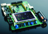
3. Since i am using a development board, it doesn't have the pin for AREF but as I checked, it is connected to Vcc.

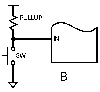
1. Detect the voltage on the V divider using a meter. Does it vary with slider position change?
2. Detect Vcc and Avcc. Are the values as expected?
3. Confirm whether Aref is configured correctly: external / internal is it connected to the ADC?
4. Same as suggested below.
5. Can you confirm the AD conversion is finished BEFORE you read the data out of ADC's register? Try to (re-) configure ADC clock to confirm ADC_conversion_completed condition BEFORE you read ADC data register.
6. Best of luck!
Adam.
1. Yes the voltage divider circuit is correct. The voltage's are as expected but it is not reflected in ADC. I even connected the ADC pin to ground but it still gives the maximum value.
2. Vcc is as Expected. But since i am using a development board, i cannot confirm about Avcc since there is no pin available for Avcc.
3. Same as Avcc. I am using a development board, no pin available for Aref so cannot confirm the value, but i think it is connected to vcc.
4. Answered above.
5. Since the data refreshes every second, i don't think it is necessary. Even if the data is read before ADC conversion is not completed, the next time it will read the correct value. But I will try with changed clock of adc and let you know. Currently i am using the ATmega32a at 1mhz and adc conversion at 500 khz.
6. Thank you, I need to have some luck on my side.
osomeim.

"Same as Avcc. I am using a development board, no pin available for Aref so cannot confirm the value, but i think it is connected to vcc."
Double check that there's not a jumper.
If you feel at all confident, measure the voltage at the pin -- there may be a fault in the board (unlikely), or some setting you need to make to have it come alive.
Double-check that you haven't left any "screw the processor" bits unset. It's common with todays way-complicated microcontrollers that you need to set up correct operation in three or four places (i.e., the ADC block, the GPIO block to connect the ADC to the pin, and the clock steering logic, to make sure that the GPIO and ADC blocks have clocks).