


Voltage swing for MSP430 PWM output
#define TIMER_PERIOD 13105
#define DUTY_CYCLE 825
void main (void)
{
//Stop WDT
WDT_A_hold(WDT_A_BASE);
//P2.0 as PWM output
GPIO_setAsPeripheralModuleFunctionOutputPin(
GPIO_PORT_P2,
GPIO_PIN0
);
//Generate PWM - Timer runs in Up mode
Timer_A_outputPWMParam param = {0};
param.clockSource = TIMER_A_CLOCKSOURCE_ACLK;
param.clockSourceDivider = TIMER_A_CLOCKSOURCE_DIVIDER_1;
param.timerPeriod = TIMER_PERIOD;
param.compareRegister = TIMER_A_CAPTURECOMPARE_REGISTER_1;
param.compareOutputMode = TIMER_A_OUTPUTMODE_SET_RESET;
param.dutyCycle = DUTY_CYCLE;
Timer_A_outputPWM(TIMER_A1_BASE, ¶m);
//Enter LPM0
__bis_SR_register(LPM0_bits);
//For debugger
__no_operation();
}
When I connect my multimeter across P2.0, I see voltage swing from [2.63,3.26]. Can someone tell me why it is not going 0 all the way?
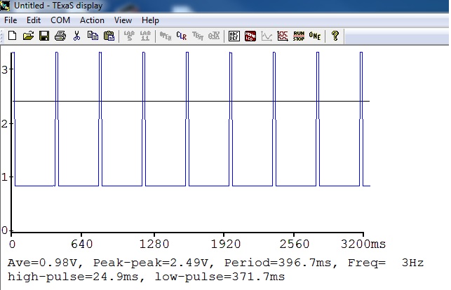
EDIT: Screenshot of waveform from software based oscilloscope.

The high pulses are supposed to go a regulator IC, which is supposed to give 5V for ON period when I gave the pulse to the regulator IC, I am not seeing any output.
Disclaimer: I have not used the MSP430 or MSPware.
Looking at a PWM waveform with a multimeter is not using the right tool. You should be using an oscilloscope instead. Your multimeter probably uses a dual slope integrator ADC and it does not respond to a changing input unless it is changing very very slowly. The comments in your code do not indicate what frequency the PWM is running at or what voltage the IO pin swings between. I suspect you are using a 3.6v supply since your measured high voltage is 3.26v.
Normally I would expect a multimeter to read values that vary around half of the output voltage with a 50% duty cycle. I do not know what duty cycle a value of 825 represents, but it appears from the values you are seeing that it is about 81.8% of 3.6v.
Average voltage: (2.63v + 3.26v) /2 = 2.945v and 2.945v is 81.8% of 3.6v.
Since you rarely will get a 3.6v output swing with a 3.6 volt supply it appears the that 825 duty cycle represents 82.5%.
The Duty cycle parameter was obtained by based off the the software oscilloscope reading. If you see from the screenshot, the ON time is 25ms much lesser than the OFF time, so I figured that multimeter should be able to register those changes.
Not sure what you mean by a SW oscope.
Set the period to one second, duty cycle 50%. Output to an LED. You should see it blink if you are truly getting an output. Then make the duty cycle 25% - you should see the change. Or setup a simple half H-bridge with some 2N2222 or LM3904 (3906?) NPN or PNP transistors and drive a little DC motor - speed a function of the the PWM.
Can you borrow a real oscope? Can you afford $350US? (plus shipping to wherever you are..)
Look at hackerspaces.org and see if there is hacker/makerspace near you. If they have been around for a while, they should have an oscope or a member has one.
Basically, you need a real tool to do serious troubleshooting.
Maybe you need a pull-down resistor or load on the PWM output, otherwise it is floating?
Umm..I doubt that, but let me try it.
A multimeter does an integration of the input voltages. Basically, it is taking an average. The swing between min and max is too fast for the multimeter.
When the meter sees the input voltage start to go low (going to 0) it tries to keep up, but its time constant is too slow. Then, while it is trying to go low, the signal goes high, so it reverses direction.
I suspect you are doing 5v logic, because of the voltages you are seeing. your meter has an average reading of 2.95 volts
this is the thing you really want to use an oscilloscope for.
You may have some success if you set the period for a few (2..3) seconds or longer. Use an LED to verify you have a very slow period. When it is dark, you are at 0v.
You need a timespan you can see the led blink


