


Improving the Reload2 active load
Introduction
With another colleague at work, we are currently developing an electronic board that will eventually be powered over Ethernet. To gain more experience with this technology, we prototyped a standalone power supply stage.
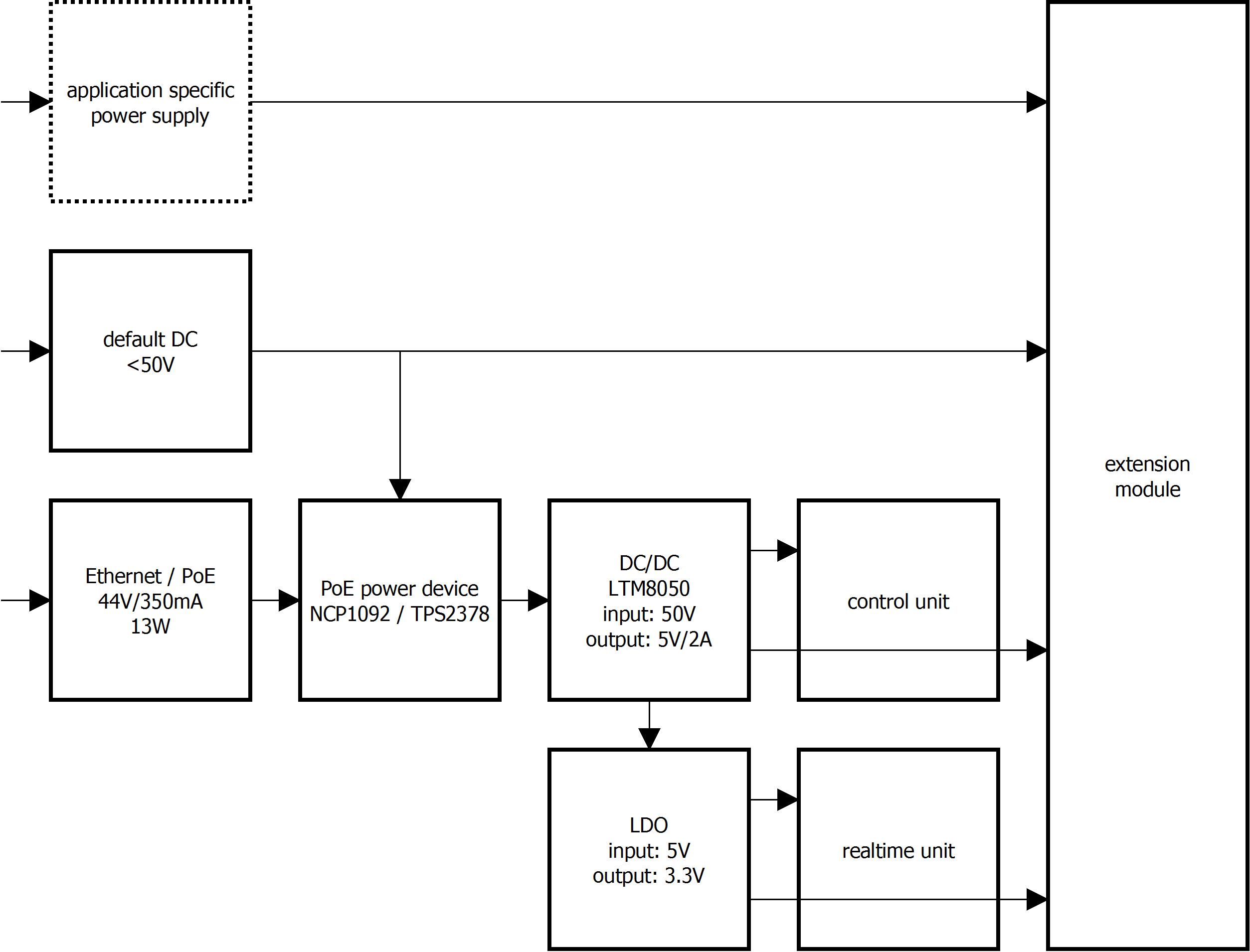
We want to test this stage with different load profiles. While we already have professional grade active loads at work, I had previously read about the Reload2 product from Arachnidlabs, a low cost active load sold on Hackaday:
http://www.arachnidlabs.com/reload-2/index.html
http://store.hackaday.com/products/re-load-2
It operates over a large range of voltage, and can handle up to 12W. Everything is provided, including heat sink and connectors. For 20$, it is very attractive so it was the occasion for me to give it a try.
The Reload2 is an open hardware project whose information can be found on the project web pages and repository:
http://www.arachnidlabs.com/reload-2/index.html
http://www.arachnidlabs.com/reload-2/instructions....
https://github.com/arachnidlabs/reload
The circuit is quite simple:
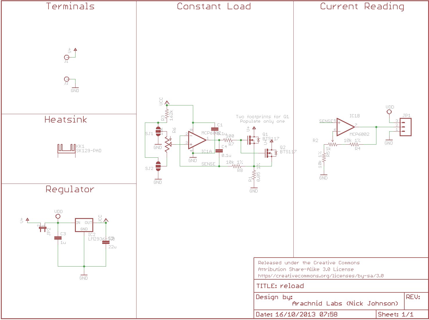
An operational amplifier drives a FET to regulate the load current. The positive input of the amplifier is set by the user with a pot, the low part of a voltage divider. The amplifier negative input is set to the voltage across a current sensing resistor of 0.05 Ohms. When regulated, the following relation exists:
u_in- = u_in+ = u_sense = r_sense * i_load
i_load = u_in+ / r_sense
i_load = u_in+ / 0.05 = u_in+ * 20
The following link explains the FET driving amplifier stage:
http://www.daycounter.com/Circuits/Current-Servo/C...
While the Reload2 is a great product, it has 2 limitations for our tests:
- the load current is set by hand,
- the minimum load current is too high.
Making the load software programmable
While setting the current by hand is fine for simple tests, it does not allow for more complex current profiles to be generated. For instance, current ramping up or down when the electronic board is booting or some components go to sleep. Thus, we need a load that is programmable. To do so, we can replace the manually controlled voltage divider by a DAC driven by a microcontroller.
For this purpose, I have a couple of Teensy3.1 boards, also bought from Hackaday:
https://www.pjrc.com/teensy/teensy31.html
http://store.hackaday.com/products/teensy-3-1
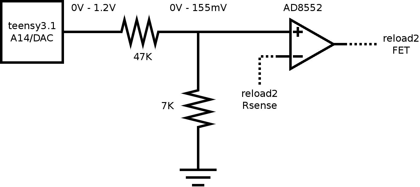
The Teensy3.1 is an electronic board relying on a Freescale MK20 ARM Cortex M4 microcontroller. In its last version, the Teensy3.1 provides a 12 bits DAC that is able to drive the Reload2 operational amplifier input. Also, it integrates an internal 1.2V voltage reference that can be used as the DAC voltage reference.
Note that we want to limit the load current to 3A, which means a DAC output voltage of 150mV. While we can limit it in software, a more interesting solution is to divide the DAC output using a resistor divider:
- it allows to use the full DAC range (0V to 1.2V at 12 bits),
- it is safer as regard with eventual software mistakes.
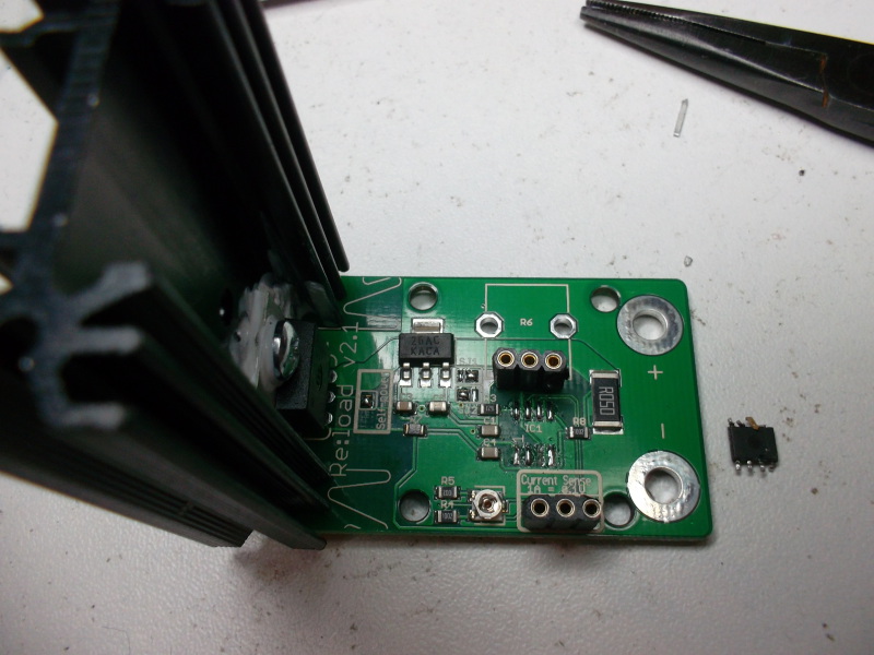
It results in the following circuit modifications:
I created a repository for the project materials:
https://github.com/texane/pload (this project specific source code)
https://github.com/texane/teensy3 (code reused across projects)
Basically, a PC program will communicate the current profile to the Teensy3.1 over serial. The current profile is described by a sequence of steps. For instance:
./a.out -const 0 1 -ramp 450 50 -wait 10 -ramp 200 50 -repeat -1
sets a constant current of 0mA for 1ms. Then, the current ramps to 450mA, with a ramp duration of 50ms. The current stays at 450mA for 10ms. Then, it ramps down to 200mA, the ramp duration being 50ms. This sequence will be repeated infinitely (-1). Below is a scope picture of the profile. The scope scale is set to 20mV and 5ms per div, and the load current is divided by 10 such that there is 100mV per amp:
Reducing minimum load current
The Reload2 uses a MCP6002 amplifier to drive the FET:
http://www.microchip.com/wwwproducts/Devices.aspx?...
http://fr.farnell.com/microchip/mcp6002-e-sn/ampli...
It is a low cost (0.4 euros), single supply, rail to rail amplifier. The datasheet states the maximum offset voltage is 4.5mV. It means that even if a 0V difference is present between the 2 inputs, the amplifier output can be as high as 4.5mV. Thus, the lowest possible Reload2 current is 0.0045 / 0.05 = 90mA. In practice, I observed a 200mA current. This is too high for our tests, as we want to validate our power supply with currents as low as a 10mA.
The solution I ended up with was to replace the MCP6002 amplifier by a chopper amplifier. Chopper amplifiers contains additional circuitry that reduces the offset voltage. Also, it corrects offset voltage drifts due to temperature. For this reason, they are also known as zero drift amplifiers:
http://electronicdesign.com/analog/chopper-stabili...
When looking for an actual component, I found the AD8552:
http://www.analog.com/media/en/technical-documenta...
http://fr.farnell.com/analog-devices/ad8552arz/amp...
Its offset voltage is 1uV, with a 0.005uV/C input offset drift. It is rail to rail and operates in the same voltage range than the MCP6002. It has the exact same footprint as the MCP6002. Thus, it can be used as a drop in replacement. Note that it is much more expensive (4.25 euros), but I guess it can be sampled for free.
Once the component was chosen, the hard part was to remove the soldered amplifier without damaging the PCB, as I did not have a hot air gun when doing it at home. I destroyed a pad due to overheat, but the mistake could still be fixed:
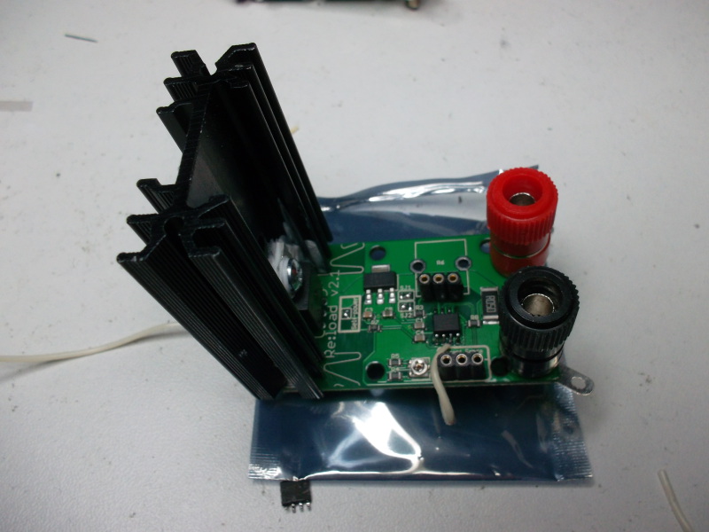
With the new amplifier and fix:
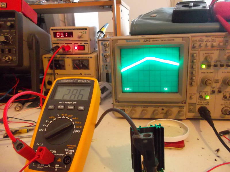
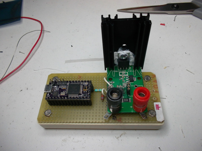
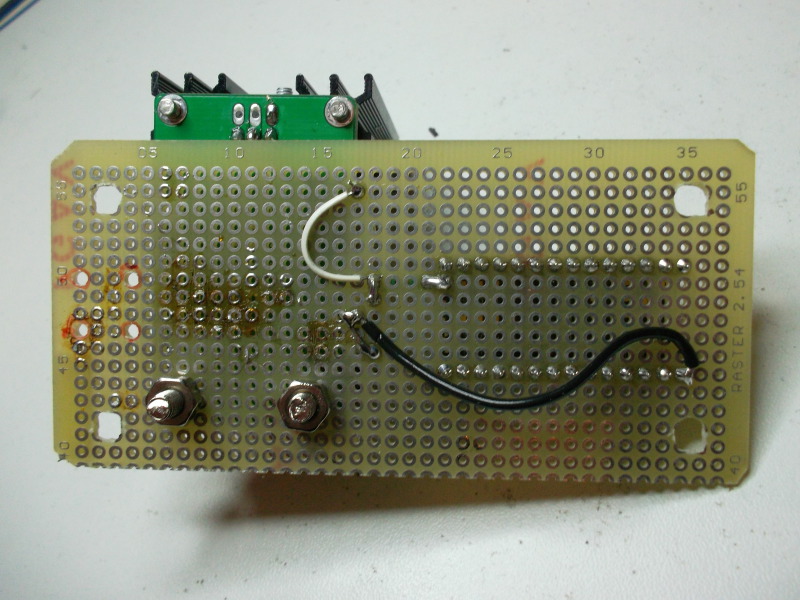
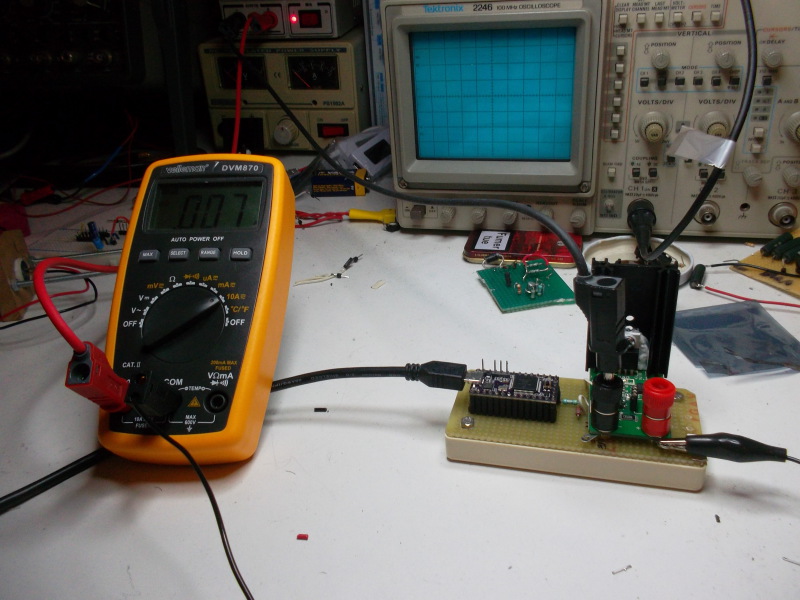
The final assembly with Teensy3.1 added:
On this picture, we see the module in use with the lowest possible current. Due to the chopper amplifier, it dropped to 7mA, which fits our requirements:
Conclusion
While it does the job quite well, it is more of a hack than a polished lab instrument. It is always interesting to repurpose stuffs, as it cultivates a knowledge different from when you start from scratch ... after all, that is mostly what hacking is about !
If you have money to spend, an alternative may be the more expensive ReloadPRO, also from Arachnidlabs and sold on Hackaday:
http://www.arachnidlabs.com/reload-pro/
http://store.hackaday.com/products/re-load-pro
I would be very interested to have feedbacks on this product !


- Comments
- Write a Comment Select to add a comment
To post reply to a comment, click on the 'reply' button attached to each comment. To post a new comment (not a reply to a comment) check out the 'Write a Comment' tab at the top of the comments.
Please login (on the right) if you already have an account on this platform.
Otherwise, please use this form to register (free) an join one of the largest online community for Electrical/Embedded/DSP/FPGA/ML engineers:


