


Quaternions and the spatial rotations in motion enabled wearable devices. Exploiting the potential of smart IMUs attitude estimation.
Wearable devices are becoming quite popular these days. Fitness trackers, medical sensors and much more implement different systems to acquire (sensors) and process user information. Among every potential design I have contributed as a researcher or engineer for a wearable system there is one that almost always was mentioned at initial stages. This is the ability to track user motion (or a specific motion analysis), even if the main purpose of the sensor system is not motion, it can potentially contribute to gather additional information from the user.
In this context, the attitude (spatial orientation) is defined with respect to a common reference frame (EARTH). Next figure will aim at clarifying this concept (Fig.1). The three-dimensional earth reference frame can be described as the directions (axis) represented by the cardinal North (N), cardinal East (E) and the earth center direction, Down (D). This is known as NED coordinates.
_62799.png) Fig.1: Graphical representation of the reference axis for Earth.
Fig.1: Graphical representation of the reference axis for Earth.
When we approach the problem of defining an object orientation in space (this is also called attitude). We want to know how this is rotated with respect to our basic reference frame (Earth axis). In simpler terms, we want to know if the side A is pointing north and the switch button on the device is pointing downwards, or any other geometrical reference we can define in our device.
Quaternions
A potential tool for describing this rotation that we can (and we want to) use is known as quaternions. Quaternions are widely employed in robotics and videogames to express spatial orientation. There are some alternatives (Euler Angles, Direction Cosine Matrix), but quaternions offer advantages and should be used when looking for the complete attitude determination. If you are curious about this, you can check the Gymbal Lock problem, quaternions don’t suffer from this.
So what's a quaternion. It is a 4-element vector, formed by a 3-dimensional vector ($\overrightarrow{v}$) and a rotation angle $\theta$ (scalar). This would be a typical quaternion ($q$):
$$ \begin{aligned} \vec{v} &= \begin{bmatrix}q_1 & q_2 & q_3\end{bmatrix} \cr q_0 &= \cos \tfrac{\theta}{2} \cr q &= \begin{bmatrix}\cos \tfrac{\theta}{2} & \sin \tfrac{\theta}{2}\cdot\vec{v}\end{bmatrix} \end{aligned} $$
Vector components $q1$, $q2$, $q3$ represents a three-dimensional vector (a direction in space) and $q0$ describe a rotation ($\theta$), the rotation amount of the reference frame across the vector $\overrightarrow{v}$. Quaternions are not easy to visualize, except for the trivial ones. Let’s imagine a couple of planes heading north (red) and east (orange) through the globe. The second reference plane required to understand how this system rotates in space is the reference frame for the plane itself. This can be defined as:
- X: Direction from the center of the airplane to the aircraft nose.
- Y: Direction from the center of the airplane to the right wing.
- Z: Downwards.
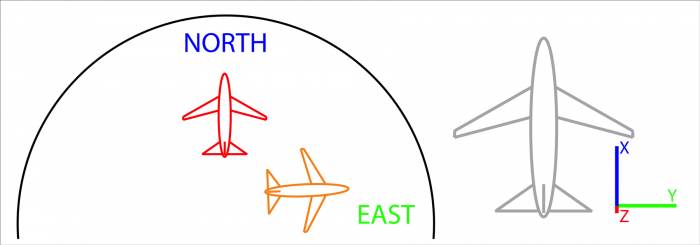 Fig.2: Two planes heading north (red) and east (orange) across the globe. Aircraft reference frame X points towards the nose, Y points to the right wing and Z points downwards.
We will know describe the spatial orientation of both airplanes (red and orange) with respect to the earth using quaternions. First case (red plane) Is perfectly aligned with earth reference frame. Plane reference frame contains three directions ($X$,$Y$,$Z$) and Earth Reference frame another three (North, East, Down). For these two reference frame to be aligned, these direction must coincide:
- $X$ and North.
- $Y$ and East.
- $Z$ and Down.
For this particular case, the translation between reference frames and can be represented by the vector $\overrightarrow{v} = [1,0,0]$ and a rotation of value zero ($\theta = 0$). Since the angle is zero the quaternion computation ($sin(0), cos(0)$) would be $q = [1,0,0,0]$. This value would represent that rotation. Question to the reader, is this rotation unique? Can a different quaternion express the same rotation?
Let’s now focus on the orange aircraft, if we observe carefully, we will notice that the plane is rotated 90º degrees towards the east. There is a change in aircraft axis with respect to the red plane and in this case, we could use some quaternions to describe the orientation change.
$$ \begin{aligned} \vec{v} &= \begin{bmatrix} 0 & 0 & 1 \end{bmatrix} \cr \theta &= 90º = \frac{\pi}{2} \end{aligned} $$
From those values we can compute the corresponding quaternion as:
$$ \begin{aligned} q &= \begin{bmatrix} cos\frac{\pi}{4} & sin\frac{\pi}{4}\cdot\vec{v} & & \end{bmatrix} \cr q &= \begin{bmatrix} 0,7071 & 0,7071 & 0 & 0 \end{bmatrix} \end{aligned} $$
Question again, is this rotation unique? Can a different quaternion express the same rotation?
A major follow-up question is, ok now I understand how quaternions describe a relation between two reference frames. How can I use them to translate directions from one to another such as a (or a set of) vector(s) which we want to track in our device to provide specific analytics or gather information from the user.
Application Example
Imagine now a wearable device. First, we need to define a reference frame and the easy path is to use the sensor reference frame ($XYZ$ sensor axis) which are described on the datasheet of any inertial motion unit (IMU). I am familiar with the Bosch Smart sensor BNO055 and in its datasheet, the default axis are described in the following figure:
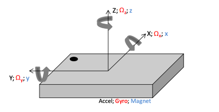
Fig. 3: Bosch BNO055 Smart Sensor IMU. Sensing axis. Reproduced from the component datasheet.
A very interesting feature of this chip is the implemented sensor fusion algorithm which directly provides the orientation data in the form of quaternion, of course we can access accelerometer, gyroscopes, and magnetometer data. The fusion process usually requires advanced filtering (such as a Kalman Filter algorithm) and is a great advantage to be able to obtain an attitude value out-of-the-box.
Now we know about quaternions, rotations and we even have a chip that can acquire those for us. So, how do we process the quaternions to obtain valuable information on the attitude of the sensing device? The analysis will need to convert directions from the sensing device ($\overrightarrow{v}$) into the earth reference frame ($\overrightarrow{u}$). Please note the subscript ($u_q$ and $v_q$) "q" since it is necessary to operate with the quaternion. $u_x$, $u_y$ and $u_z$ are the components for vector $\overrightarrow{u}$, similarly $v_x$, $v_y$ and $v_z$ compose vector $\overrightarrow{v}$.
$$ \begin{aligned} \vec{v_q} &= q \odot u_q \odot q^t \cr \vec{u_q} &= q^t \odot v_q \odot q \end{aligned} $$
Where
$$ \begin{aligned} u_q &= \begin{bmatrix} 0 & u_x & u_y & u_z \end{bmatrix} \cr v_q &= \begin{bmatrix} 0 & v_x & v_y & v_z \end{bmatrix} \cr q_t &= \begin{bmatrix} q0 & -q1 & -q2 & -q3 \end{bmatrix} \cr \end{aligned} $$
And $\odot$ denotes the Hamilton product of the quaternion vector, a mathematical operation defined as:
$$ \begin{aligned} A \odot B &= \begin{bmatrix} a_0b_0-a_1b_1-a_2b_2-a_3b_3 \\ (\;a_0b_1-a_1b_0-a_2b_3-a_3b_2\;) \; \textbf{i} \\ (\;a_0b_2-a_1b_3-a_2b_0-a_3b_1\;) \; \textbf{j} \\ (\;a_0b_3-a_1b_2-a_2b_1-a_3b_0\;) \; \textbf{k} \end{bmatrix} \end{aligned} $$
The result of both transformations expresses the same vector (direction) with respect to either reference frame. This is useful for tracking specific vectors of the sensing device across the space orientation sphere. For instance, imagine we have a device placed in the ankle of a person (figure 4). This image illustrates an example device sensor reference frame which of course is the one described by the internal PCB prototype created for this application.
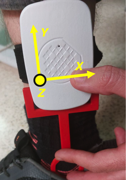
Fig. 4: Sensor positioning and sensor reference frame illustration. Reproduced from IEEE Access Article.
Next stage would be to define a vector which we will track. This vector is representing a specific direction on the device. In our case we will use ($\overrightarrow{S_v} = [0, -1, 0]$) which in the sensor reference frame is pointing downwards (check above image). We can apply equations introduced before to compute the vector direction in the earth reference frame ($S_u$). The rest is analyzing the direction of $S_u$ to evaluate our application requirements. In this article we are aiming at following user activity level and position (standing / walking / laying down) across the day from measurements in the ankle.
A quick method to determine whether the vector Su tracking is hitting a certain spatial orientation region is to define those regions in the unitary sphere and then check the directions of the vector in the earth coordinates ($S_u$) to analyze if it is within the potential regions of interest. Whenever there is a match we can compute that orientation as either horizontal (magenta region) where the ankle is horizontal to the ground and person is most likely laying down, or vertical (cyan region) where the ankle is vertical to the ground and the user is either sitting down or standing/walking.
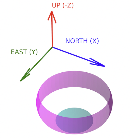
Fig. 5: Definition of specific regions in 3D-space to classify a device orientation. Reproduced from IEEE Conference DCIS 2022.
Conclusions
The Bosch Smart Sensor BNO055 is an amazing chip capable of returning attitude value of the sensing device by performing a complex sensor fusion algorithm on its own and just providing the result in the form of quaternions. This is a great tool for systems engineers since it can allow us to track orientations in space right away.
Quaternions are friendly though not very straightforward, they are hard to visualize (unlike euler angles), but provide a complete solution to the problem and do not suffer from the Gymbal lock problem. The major utility is to perform rotations across different reference frames (which is exactly the mathematical problem defined by the IMU motion tracking).
Applications for motion tracking are limitless, there’s every reason to evaluate and test orientation tracking for wearable devices, since it can provide an additional insight into the user experience, behavior and generate new potential use cases. Even as a side partner for different kind of sensors an IMU can provide some error detection tools by the detection of motion artifacts.


- Comments
- Write a Comment Select to add a comment

Good article. I'd suggest some improvements in your MathJax though, using semantic markup like bmatrix, vec, tfrac, and aligned:
instead of
\overrightarrow{v} = [\quad q_1 \quad q_2 \quad q_3 \quad] \qquad q_0 = cos(\frac{\theta}{2})
q = [\quad cos(\frac{\theta}{2}) \quad sin(\frac{\theta}{2})\cdot\overrightarrow{v}\quad]
try
\begin{aligned}
\vec{v} &= \begin{bmatrix}q_1 & q_2 & q_3\end{bmatrix} \cr
q_0 &= \cos \tfrac{\theta}{2} \cr
q &= \begin{bmatrix}\cos \tfrac{\theta}{2} & \sin \tfrac{\theta}{2}\cdot\vec{v}\end{bmatrix}
\end{aligned}
For example:
$$\begin{aligned} \vec{v} &= \begin{bmatrix}q_1 & q_2 & q_3\end{bmatrix} \cr q_0 &= \cos \tfrac{\theta}{2} \cr q &= \begin{bmatrix}\cos \tfrac{\theta}{2} & \sin \tfrac{\theta}{2}\cdot\vec{v}\end{bmatrix} \end{aligned}$$

Thank you very much! I have included the MathJax syntax for every formula and is more readable now :)!
Hi Pablo - A question at the very beginning, about the orange aircraft headed East.
You give the NDE vector as [-1,0,0].
I expected [0,1,0].
Can you explain?
Thanks!
Hello, you are absolutely right, there was a mistake on the text. In NED coordinates, orange plane is rotated 90º over the down axis (D)...
Thanks for noticing!
Best regards!
Thanks, still confused, now you show [0,0,1]; I expected [0,1,0].
Which is correct?
I understood v is the NDE typo NED vector?
Did I not understand correctly?
Thanks!
I believe the confusion might be from the order. I'm using in this article (North East Down) NED coordinates. At the same time you are mentioning NDE (North Down East), notice how the Down direction is the one in the vector v in both cases.
o
Sorry I can't type, meant NED.
So the orientation of the orange aircraft in NED coordinates is:
v = [ n=0, E=1, D=0 ]
So, is V really the orientation in NED coordinates, or something else?
I'm really not following what you've written, sorry...V is a vector, that represents the direction of the quaternion. (Think of this a vector upon which the plane will rotate to transform its orientation into the other plane orientation).
Quaternions are hard (impossible really) to visualise, except the trivial ones, that's why I was describing the trivial quaternion to rotate from North to East, using the (0,0,1) vector at an angle of 90º.
Hopefully this will make sense to you!
To post reply to a comment, click on the 'reply' button attached to each comment. To post a new comment (not a reply to a comment) check out the 'Write a Comment' tab at the top of the comments.
Please login (on the right) if you already have an account on this platform.
Otherwise, please use this form to register (free) an join one of the largest online community for Electrical/Embedded/DSP/FPGA/ML engineers:


