


Understanding Microchip 8-bit PIC Configuration
This second in a series of five blog posts continues exploring getting started with Microchip’s 8-bit PIC family of microcontrollers by delving into basic processor memory organization and how this family of microcontrollers initialize, specifically:
- PIC Memory & Registers
- PIC Configuration Sources
- Revisiting MPLAB X Project Creation
- MCC Generated Code Exploration
PIC®, MPLAB® X, and PICkit™ 4 are trademarks of Microchip Technology Inc.
All data sheet references are to Microchip document PIC18F27_47Q10-data-sheet-40002043C, © 2019 - Microchip Technology Inc, available at the time of post publishing here.
PIC Memory & Registers
While this post does not attempt to completely explore the memory architecture of the processor family, a basic understanding of memory types and basic organization within the processor helps to understand the broad role registers play. On chip memory of the PIC18 high-end devices comes in two primary flavors, static RAM and flash memory. Contents of flash memory persists after the power to the microcontroller is removed; it is where application code is stored when the application is compiled and uploaded to the microcontroller via the PICkit 4 programmer / debugger. Unlike flash memory, static RAM does not persist when the power to the microcontroller is removed; it is “working” memory whose content changes frequently through reads and writes as part of program execution.
The Data Memory Organization (heading 10.3 of section 10 Memory Organization) of the PIC18F47Q10 datasheet refers to the static RAM in the controller as data memory. This data memory is broken up into 256-byte banks. As the PIC18 family is based on an 8-bit architecture, the smallest atomic unit of memory is 8 bits wide – one byte, hence the bank consisting of 256 bytes, an amount evenly divisible by 8. This data memory element can be thought of as consisting of memory for two purposes, registers and application memory.
The registers always occupy a specific address in data memory. Application memory contents are managed by the executing
application. The PIC18 family has two types of 8-bit
registers, from the datasheet they are Special Function Registers
(SFRs) and General-Purpose Registers (GPRs). GPRs can be
thought of as scratch pads for the processor. An example of
GPR use would be when the current instruction is adding two bytes
– the two operand bytes would typically be placed in GPRs and then
moved into the ALU for the addition operation; most likely the output of
the ALU operation would then be placed in yet another, or perhaps one
of the same GPRs. Three instructions later those same GPRs
could hold two completely different values.
The primary registers of interest in this post are Special
Function Registers – SFRs. A primary use of SFRs is control and
status of processor peripherals. As mentioned previously, SFRs, like
all registers in the family, are 8 bits wide. The processor
managed GPIO (General Purpose Input-Output ) SFRs provide
functionality such as holding the logic value (0/1) of processor
pins, determining if a particular set of pins (a port) are inputs or
outputs, or if the pins have weak pull up resistors enabled. Other SFRs configure how communication busses such as SPI and I2C operate or how a timer behaves as
well as the current count of the timer.
Revisiting MPLAB X Project Creation
A quick highlight of the steps enumerated in the first post of this series creating the MPLAB X project for the PIC18F47Q10 is
provided below. For more details around the steps to create an MPLAB X
project and even installing the IDE if you have not yet done so,
please see the first post in this series
1. Launch MPLAB X
2. Create a new Standalone Project type
3. Select the correct device - the 8-bit PIC18F47Q10 and programming / debugging tool – the PICkit 4 in-circuit debugger
5. Select a version of the 8-bit compiler to use
6. Enter a project name
7. Immediately after the project is created, ensure Use low
voltage programming mode entry
is selected (project properties /
PICKit4 / PICKit4 Tool Options) – if low voltage programming is not selected,
processor damage can result!
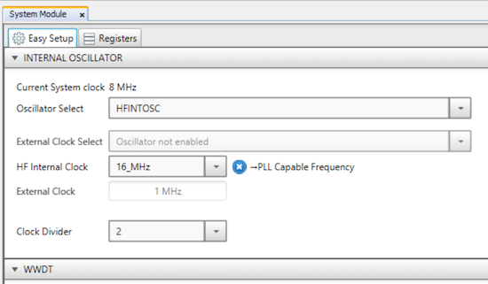
After creating the project, MCC (MPLAB Code Configurator) is used to configure the clock system of the PIC18F47Q10 to use the on chip (internal) high frequency oscillator running at 16MHz with a 2:1 clock divider resulting in a processor clock speed of 8 MHz. Additionally, the configuration routes the clock output to Port / Pin A6 of the 40 pin PDIP PIC18F47Q10 package. The first project additionally configured Port/Pin A4 as GPIO output, starting with an output set to logic high (1), however, GPIO is covered in-depth in a subsequent post and not addressed here.
Once configured in the MCC GUI, The System Module-Easy Setup tab should appear as:
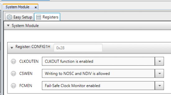
And the System Module-Register CONFIG1H should match the following configuration:
Once the configuration is set within MCC, click Generate to have MCC generate the necessary code to implement the requested configuration and add the code to the current project.
Understanding the Specified MCC Configuration
The project configuration above used MCC to graphically configure
the oscillator selection, final clock configuration, and routing of
the clock signal to an output pin of the PIC18F47Q10. This is a
subset of the full suite of MCC’s capabilities. MCC can also
manage basic GPIO port configuration, interrupt configuration and enable and configure peripherals such as SPI, I2C and USART. The oscillator selection and the related clock configuration are some
of the more complicated configurations with the 8-bit controllers as some of that
configuration needs to be in place and available to the processor
as it starts up. Without at least an initial clock
configuration the processor cannot run. While the vast
majority of configuration – such as setting up GPIO or serial
communications can be completed as part of application code
executing after the processor starts, the processor
implementation needs a means to provide some configuration
statically for reading during startup. Understanding the code generated via MCC can help shed some light on the more complex pre-code execution oscillator configuration and selection functionality as well as initial clock configuration.
PIC Configuration Sources
The PIC18F47Q10 has two sources for configuration – Configuration
Words and SFRs. Both methods rely on SFR registers,
the difference lies in where the registers are in memory and how /
when the registers are written.
Configuration Words
On the PIC 8-bit family, a word size is 16 bits. As all PIC18F47Q10 registers are 8-bits, the 16 bit wide configuration words are realized by two 8-bit registers occupying consecutive physical memory locations.
As the elements managed through configuration words are values the processor needs to be available upon startup, those values need to persist across power cycles. Therefore these values reside in flash. Recall that flash memory is written as part of the chip programming managed by MPLAB X and the PICkit 4 programmer / debugger (or the tool being used to program the processor).
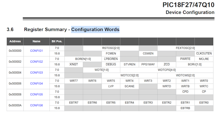
Turning to the processor datasheet, Section 3 – Device Configuration , the processor has six Configuration Words, Configuration Word 1 through Configuration Word 6 residing at memory locations 300000h through 30000Bh. The memory occupied by these six 16 bit long (word) registers is 0x0B (12d) bytes – validating the previous statement of 8 bit register architecture in general, with a word being two 8-bit bytes.
Section 3.6 of the datasheet presents a summary of the six Configuration Words.
The CONFIG1 configuration word contains those settings related to oscillator and clock management of interest in the application. The
other configuration words deal with settings such as memory
protection, watchdog timer, code protection, etc.
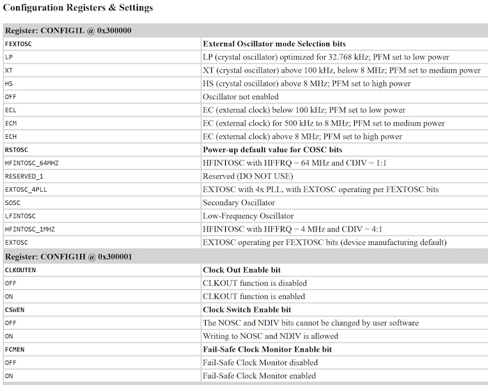
Looking at data sheet’s CONFIG1 definition (section 3.7.1):
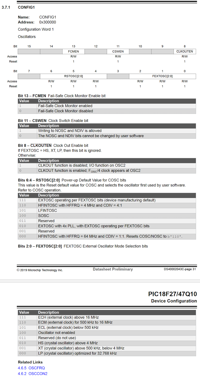
Bits 2:0 control / configure the external oscillator selection. The project uses the High Frequency Internal Oscillator which equates to not needing to enable any external oscillator. The value to use is 100b - Oscillator not enabled. The lowercase 'b' after the value indicated the value is expressed as binary.
Bits 6:4 control / configure the Current Oscillator multiplexer select bits which determines which oscillator is used on reset. The how and where this multiplexer fits into the clock source can be found in the datasheet section 4 - Oscillator Module, specifically Figure 4.1 COSC<2:0>:
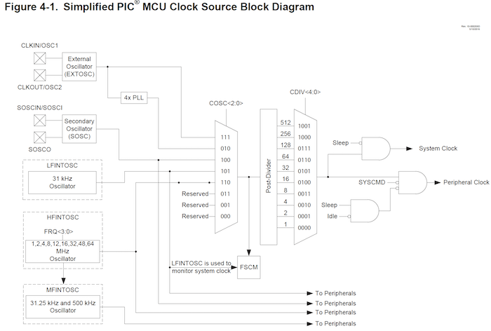
To select the High Frequency Internal Oscillator (HFINTOSC) for this project the RSTOSC (ReSeT OSCillator) value should be 110b. Note that with that value, the initial frequency of the oscillator is also set to 4 MHz (HFFREQ) and the clock divider is set to 4:1 (CDIV). These values start the processor with a 1MHz clock. Without a subsequent configuration the processor runs with a 1MHz system clock. However, the actual final speed of the high frequency internal oscillator and clock divider required by the application can be further configured in user code once the processor is running; the CONFIG1 configuration word sets a default internal high frequency oscillator configuration to get things started.
Bit 8 configures the clock signal output to OSC2 unless FEXTOSC = HS, XT or LP. As this project is using HFINTOSC, setting this bit to 0b (note that the data sheet indicates this pin is driven via inverted logic levels) routes FOSC/4 at OSC2.
As the CONFIG1H (as well as the other configuration word values) is written to flash to be to be available at processor startup, the compiler must provide a means to specify, as part of the project source code, those values which need to be written to processor flash during the microcontroller memory programming step. The configuration word settings are included as part of the source via #pragma statements. Within C programs, such statements specify compiler directives which are implementation specific – in this case toolchain specific. As the toolchain compiles and assembles the program resulting in a binary image to write to processor memory, the #pragma statement used with the specified configuration words indicate those configuration values that need to be written to specific memory locations as defined by the target processor.
SFRs
The vast majority of configuration of PIC18F47Q10 peripherals occurs post processor start up as part of the application code – often as a one-time initialization sequence. This configuration is completed by writing specific bits in SFRs dedicated to internal processor peripherals such as communication (serial, I2C, SPI), timers, interrupts and GPIO. The available peripherals as well as the related registers descriptions are covered in the datasheet. For the current project, the final clock speed of 8MHz is shaped through setting SFRs controlling both the oscillator speed and clock dividers after the project is started with the 1MHz clock speed previously discussed.
MCC Generated Code Exploration
With a better understanding of what to look for as well as how to interpret the values once found, examination of the MCC generated code can provide additional insight on how the selected oscillator and clock configuration are applied.
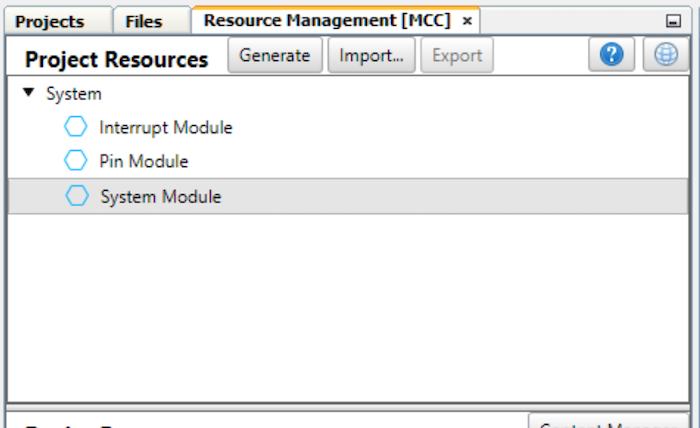
Clicking Generate in the Resources Management [MCC] tab, starts the MCC generation of C code which is inserted into the current project. The generated files can be found and opened from either the Projects tab or the Files tab of the MPLAB X IDE. Which one to use is mostly a matter of preference.
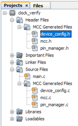
The Projects tab provides more overall structure, such as grouping files into virtual project folders (virtual as these folders do not exist in the actual project source on disk), based on file type: Headers, Source, Libraries, etc. These groupings often require a few extra clicks to get to specific file. Of interest in this tab are the Header Files and Source Files project folders with each having a child project folder, MCC Generated Files. The respective generated header and source files reside in these two leaf folders.
The Files tab mirrors the actual disk structure of the project. Here, the mcc_generated_files folder contains the files of interested – the MCC generated header and source files. Within each of the containers is an MCC Generated Files container. Expanding both of those provides access to the generated files of interest.
For the remainder of this section the screen captures and discussion is presented from the Projects tab perspective.
Header File Structure
Understanding how the hierarchy of headers are included into an MPLAB X project and the structure as well as content of those headers is paramount to understanding both the SFR definitions and the bit masks that enable working with processors peripherals using datasheet names and definitions
Starting at the primary project level file, main.c MCC generated code includes in the mcc.h file - note mcc.h is still a project level include file:
#include "mcc_generated_files/mcc.h"
On the Windows platform, MPLAB X opens a file in a new tab by holding the CTRL key
The mcc.h file includes another important file: xc.h.
#include <xc.h>
Along with some definitions, xc.h in turn includes pic18.h.
#include <pic18.h>
Continuing to unravel the header include chain, the pic18.h system header is responsible for including pic18_chip_select.h.
#include <pic18_chip_select.h>
This file, based on the processor selected for the project via symbol definition within the project, includes the processor specific file containing symbol definitions for the processors SFRs as well as masks for setting individual and groups of bits to manage peripheral behavior through the related SFRs.
For the PIC18F47Q10, the system level include file pic18f47q10.h (line 248) is included because of the definition of the _18F47Q10 symbol within the project as:
#ifdef _18F47Q10
#include <pic18f47q10.h>
#undef _HEADER_NOT_FOUND
#endif
The pic18f47q10.h file is rather large at over 2MB; as such the IDE issues a warning that the file size could cause an OutOfMemory error corrupting the IDE. The file can always be opened directly from the file system with a system text editor for viewing.
Returning to the MCC generated project header, mcc.h, reveals additional project level headers generated by MCC; of interest in this post is device_config.h. There is also pin_manager.h, which is not explored in this post.
#ifndef MCC_H
#define    MCC_H
#include <xc.h>
#include "device_config.h"
#include "pin_manager.h"
#include <stdint.h>
#include <stdbool.h>
#include <conio.h>
These two header files loosely map to the MCC Project Resource modules, Pin Module (pin_manager.h) and System Module (device_config.h), used to configure the processor via the MCC GUI.
The mcc.h header file also defines the functions for initializing the system as well as the oscillator:
/**
 * @Param
    none
 * @Returns
    none
 * @Description
    Initializes the device to the default states configured in the
 *                  MCC GUI
 * @Example
    SYSTEM_Initialize(void);
 */
void SYSTEM_Initialize(void);
/**
 * @Param
    none
 * @Returns
    none
 * @Description
    Initializes the oscillator to the default states configured in the
 *                  MCC GUI
 * @Example
    OSCILLATOR_Initialize(void);
 */
void OSCILLATOR_Initialize(void);
Setting the Configuration Words
The device_config.h header file is not all that interesting other than it provides a definition of and value for the symbol _XTAL_FREQ. Although the project does use not an actual crystal but rather the high frequency internal oscillator, the symbol is used in areas of the application and system functions that need-to-know processor speed.
The corresponding implementation file, device_config.c contains the #pragma compiler directives previously discussed. The values specifically set as part of this project within the MCC GUI are reflected in the setting of the CONFIG1 values. Recall that the PIC18F47Q10 is an 8-bit processor, so each register is 8 bits, the size of a word is two bytes, hence the code sets to 8-bit registers, CONFIG1L and CONFIG1H.
// CONFIG1L
#pragma config FEXTOSC = OFF    // External Oscillator mode Selection bits->Oscillator not enabled
#pragma config RSTOSC = HFINTOSC_1MHZ    // Power-up default value for COSC bits->HFINTOSC with HFFRQ = 4 MHz and CDIV = 4:1
// CONFIG1H
#pragma config CLKOUTEN = ON    // Clock Out Enable bit->CLKOUT function is enabled
#pragma config CSWEN = ON    // Clock Switch Enable bit->Writing to NOSC and NDIV is allowed
#pragma config FCMEN = ON    // Fail-Safe Clock Monitor Enable bit->Fail-Safe Clock Monitor enabled
The generated code is not using the actual raw bit values for the specific settings, but rather much more (human) readable constants such as FEXTOSC = OFF instead of directly setting bits 2:0, of the CONFIG1L register to the needed value of 100b. Instead, the code is using constants more closely aligned with the terminology found in the datasheet. The specific values that are available, such as FEXTOSC or RSTOSC are not defined in the datasheet, nor are they defined in processor include file, pic18f47q10.h, looked at earlier. Because these are compiler directives the available symbols and their meaning are defined in the compiler documentation. There is an HTML file containing the settings and named values for each of the configuration registers (two registers, High and Low for each configuration word in the datasheet). These files can be found in the docs/chips sub-folder structure within the compiler installation directory. As sample of the file for the PIC18F47Q10 (18f47q10.html) documents:
For the previously discussed CONFIG1L bits:6:4, the RSTOSC (ReSeT OSCillator) the compiler directive uses the constants defined in the processor documentation:
#pragma config RSTOSC = HFINTOSC_1MHZ // Power-up default value for COSC bits->HFINTOSC with HFFRQ = 4 MHz and CDIV = 4:1
The value of HFINTOSC_1MHZ for the parameter RSTOSC sets the initial
COSC (Current OSCillator) to the high frequency internal oscillator
running at 4 MHZ with a clock divider of 4:1. This configuration results in a processor clock speed of 1 MHz immediately after start up. However, he
project was configured, via MCC, for an 8MHz processor speed - additional configuration will be needed.
The remainder of the device_config.c file contains the MCC generated values for the other five configuration words (registers). As the project’s configuration requirements did not change any of these other values, MCC generated “defaults” for the project. Using the techniques used to dissect the CONFIG1L and CONFIG1H registers, investigating the remainder of the configuration word settings should be straight forward.
Setting the Configuration SFRs
Once the processor is up and running with an initial oscillator source / speed and a specific divider, the oscillator configuration can be changed by application code writes to special function registers to ultimately set the processor clock at the speed needed for the project. As previously seen, the project level include file, mcc.h provides a function declaration for oscillator initialization, OSCILLATOR_Initialize(void):
/**
  * @Param
    none
 * @Returns
    none
 * @Description
    Initializes the oscillator to the default states configured in the
 *                  MCC GUI
 * @Example
    OSCILLATOR_Initialize(void);
 */
void OSCILLATOR_Initialize(void);
The function is called as part of the SYSTEM_Initialize method, also declared in mcc.h:
/**
 * @Param
    none
 * @Returns
    none
 * @Description
    Initializes the device to the default states configured in the
 *                  MCC GUI
 * @Example
    SYSTEM_Initialize(void);
 */
void SYSTEM_Initialize(void);
The SYSTEM_Initialize method is implemented in mcc.c:
void SYSTEM_Initialize(void)
{
    PMD_Initialize();
    PIN_MANAGER_Initialize();
    OSCILLATOR_Initialize();
}
The implementation of OSCILLATOR_Initialize(void) (defined in mcc.h) is also found in mcc.c:
void OSCILLATOR_Initialize(void)
{
    // NOSC HFINTOSC; NDIV 2;
    OSCCON1 = 0x61;
    // CSWHOLD may proceed; SOSCPWR Low power;
    OSCCON3 = 0x00;
    // MFOEN disabled; LFOEN disabled; ADOEN disabled; SOSCEN disabled; EXTOEN disabled; HFOEN disabled;
    OSCEN = 0x00;
    // HFFRQ 16_MHz;
    OSCFRQ = 0x05;
    // TUN 0;
    OSCTUNE = 0x00;
}
This code sets the various SFRs associated with the PIC18F47Q10’s Oscillator Module – covered in Section 4 of the datasheet. Reviewing some of the code, specifically,
OSCCON1 = 0x61;
sets the OSCCON1 (OSCillator CONtrol Register 1) an SFR at address 0xED3 to 0110 0001b.
The processor specific header file pic18f47q10.h contains the symbol definition for OSCCON1:
// Register: OSCCON1
#define OSCCON1 OSCCON1
extern volatile unsigned char           OSCCON1             __at(0xED3);
#ifndef _LIB_BUILD
asm("OSCCON1 equ 0ED3h");
#endif
The data sheet shows OSCCON1 contains two setting for the new oscillator, the requested new oscillator source - Bits 6:4 NOSC[2:0] and the requested new the clock divider Bits 3:0 NDIV[3:0].
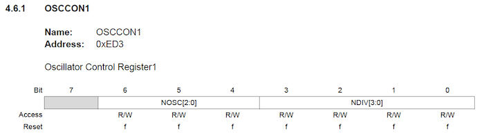
The values being set for the new oscillator – 110b specify the HFINTOSC (High Frequency INTernal OSCillator):
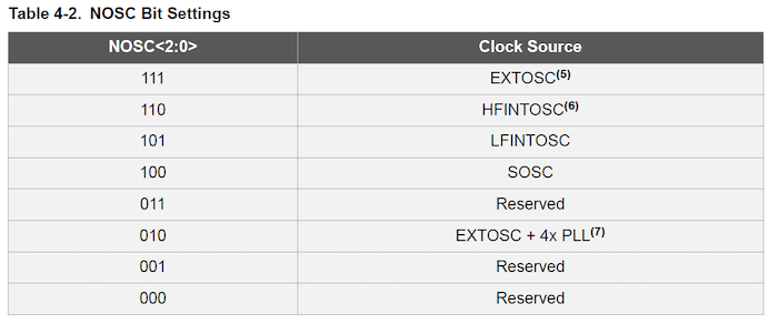
With a Clock Divider of 2 (2:1):
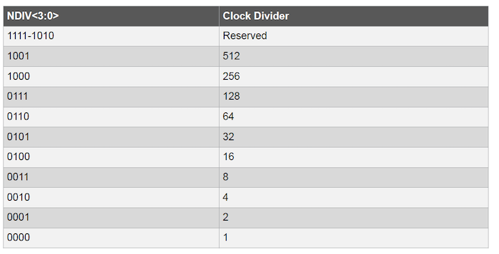
This sets the new processor clock to 4MHz / 2 or 2 MHz. There is clearly even more configuration needed to get to the requested clock frequency of 8MHz -16MHz HFINTOSC frequency with a CDIV of 2.
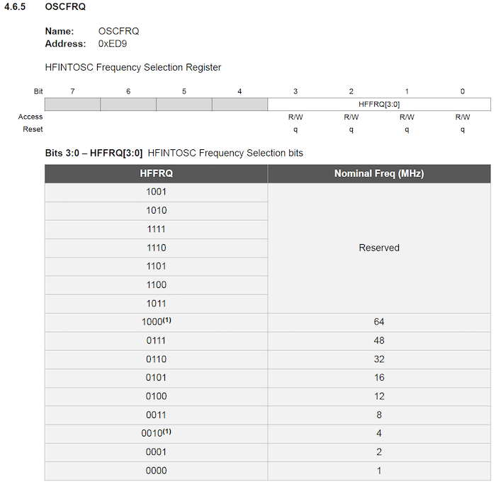
Continuing to review the Oscillator Module control registers, the OSCFRQ SFR looks like a good candidate. Looking at how the MCC generated code sets OSCFRQ:
OSCFRQ = 0x05;
It appears that MCC is setting OSCFREQ Bits 3:0 (HFFRQ[3:0]) to 0101b, which matches the 16MHz configured in the MCC GUI:
As can be seen in remainder of the OSCILLATOR_Initialize() implementation, MCC generated code configuring some additional oscillator control registers. As the project’s configuration requirements did not specifically change any of these other values, MCC generated “defaults” for the project. Using the techniques used to dissect how the oscillator control registers were used by MCC to change the clock speed to the configuration specified 8 MHz, investigating the remainder of the generated in OSCILLATOR_Initialize() method is straight forward.
Summary
The post started with a look at PIC memory organization and the concept of registers. After a quick review of project creation detailed in a prior post, this post explored configuration sources, including Configuration Words and SFR, and how the former solves the issue of providing oscillator and clock settings needed as the processor is starting. Finally looking at a code generated through MCC for the specified project configuration demonstrated how Configuration Words values are set via compiler directives for values needed at processor start up as well as how SFRs can update the oscillator configuration with application code to fine tune the processor clock configuration. While not particularly complex, configuring the startup oscillator selection and clock speed is more complex than many configuration tasks due to the need to program flash locations via compiler directives to get the processor started and then through SFRs once the processor is started. It is managing these complexities where MCC can be very helpful in getting a basic project structure in place for getting the processor started.


- Comments
- Write a Comment Select to add a comment

I appreciate you writing this series, Luther! I'm a fan of PICs, exactly because they are one of the only MCUs to still come in a DIP package, like you mention. They also have a really unique set of peripherals in many cases! I feel like the Combinational Logic Cell that is on some of the mid-range PICs could be an extremely useful peripheral for a lot of applications.
I ran into an interesting problem a few months ago related to the PIC's memory organization that I was wondering if you could answer. I was creating an array in main and when it exceeded about 60 or 70 bytes, I would get an "out of memory" error when I tried to compile (as in, my program exceeded the memory available on my PIC). I'm fairly certain this was related to the fact that RAM is paged, like you mention, with each page being 80 bytes on the PIC I was using (I'm assuming that there were a few other local variables that, combined with my array, were exceeding 80 bytes). I had thought, though, that the compiler can emit instructions to make these 80 byte pages look like one contiguous region of memory and, in fact, when I declared my array as static my program compiled with no problems. Have you ever run into that issue? Is there any different solution than making my variables static? The solution I came up with just feels so klunky to me and not scalable; what if I need more than 20 32-bit integers in my function? Do I just need to declare enough of them static so that I don't exceed the 80 byte limit? Anyway, thanks for any help you can provide!

void main(void) {
    int largeArray[100];
    while(1) {
        for(int loopIteration=1; loopIteration < 3; loopIteration++) {
            for(int largeArrayIndex = 0; largeArrayIndex < 100; largeArrayIndex++) {
                largeArray[largeArrayIndex * loopIteration] = largeArrayIndex;
            }
        }
    }
    return;
}
Memory Summary:The PIC family does not page memory as you mentioned. Paging is an operating system concept in which “pages” of memory are swapped between secondary storage (often a disk) and actual memory to provide an available virtual memory space that is larger than the actual available RAM. In this case, any memory usage in PIC applications is actual physical memory usage as there is no OS and no external storage source.
Program space used BCh ( 188) of 20000h bytes ( 0.1%)
Data space used D2h ( 210) of D1Fh bytes ( 6.3%)
Configuration bits used 6h ( 6) of 6h words (100.0%)
EEPROM space used 0h ( 0) of 400h bytes ( 0.0%)
ID Location space used 0h ( 0) of 100h bytes ( 0.0%)
To post reply to a comment, click on the 'reply' button attached to each comment. To post a new comment (not a reply to a comment) check out the 'Write a Comment' tab at the top of the comments.
Please login (on the right) if you already have an account on this platform.
Otherwise, please use this form to register (free) an join one of the largest online community for Electrical/Embedded/DSP/FPGA/ML engineers:


