


Peripheral Interaction Without a Linux Device Driver Using Spidev
Overview
When integrating a new peripheral onto an embedded Linux platform, we might think we always need to implement a kernel module to serve as a device driver. However, as we all know, absolutes such as “always” and “never” are rarely true. The same is true in this case. Implementing a device driver in kernel space on an embedded Linux platform should only be undertaken if the performance requirements of the final application demand it. In most instances, a userspace implementation is sufficient. In this blog post, we will walk through how to use a common framework in embedded Linux – called “spidev” – to implement an application to interface with a peripheral over the SPI bus. We will use a Toradex Apalis iMX8 SoM with an Ixora carrier board (https://www.toradex.com/computer-on-modules/apalis-arm-family/nxp-imx-8) communicating with a Bosch BM388 pressure sensor (https://www.bosch-sensortec.com/products/environmental-sensors/pressure-sensors/bmp388/).
Laying the Foundation
Before the spidev framework can be used, modifications must be made to the device tree so that the kernel exposes the appropriate device to userspace applications. Luckily, the device tree that Toradex provides to work with the Apalis SoM already has the appropriate entries:
/* Apalis SPI1 */
&lpspi0 {
    .
    .
    .
    spidev0: spi@0 {
        compatible = "toradex,evalspi";
        reg = <0>;
        spi-max-frequency = <4000000>;
    };
};
Before 2015, adding a spidev node in the device tree was sufficient without the “compatible” field. However, that year, a patch was introduced (https://patchwork.kernel.org/project/spi-devel-general/patch/1427499742-26916-1-git-send-email-broonie@kernel.org/) would result in the kernel complaining if a spidev node is incorrectly added to the device tree. The reasoning was that the device tree is a description of the hardware, but spidev is simply a framework to access hardware. Thus, having the spidev node as it existed before the patch was not in the spirit of the device tree and was incorrect. The patch required a compatible field in the spidev node to correct this, which is common for all nodes describing hardware in the device tree.
However, let's look at the spidev driver in the upstream kernel (under drivers/spi/spidev.c). We can see that the compatible strings (which are used to associate a device driver to a node in the device tree) don’t contain “toradex,evalspi”:
static const struct of_device_id spidev_dt_ids[] = {
        { .compatible = "rohm,dh2228fv", .data = &spidev_of_check },
        { .compatible = "lineartechnology,ltc2488", .data = &spidev_of_check },
        { .compatible = "semtech,sx1301", .data = &spidev_of_check },
        { .compatible = "lwn,bk4", .data = &spidev_of_check },
        { .compatible = "dh,dhcom-board", .data = &spidev_of_check },
        { .compatible = "menlo,m53cpld", .data = &spidev_of_check },
        { .compatible = "cisco,spi-petra", .data = &spidev_of_check },
        { .compatible = "micron,spi-authenta", .data = &spidev_of_check },
        {},
};
The simple fix would be to simply add the following line to the list, compile and push up the kernel to our board:
.
.
.
        { .compatible = “toradex,evalspi”, .data = &spidev_of_check },
        {},
};
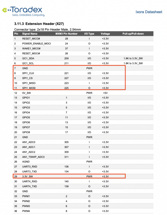
Before implementing and running our application, we must determine the pinouts on the Toradex Apalis Ixora board. We can review the datasheet of the board (https://docs.toradex.com/101430-apalis-arm-ixora-datasheet.pdf) and identify the appropriate pins on the X27 extension header in section 3.11.3:
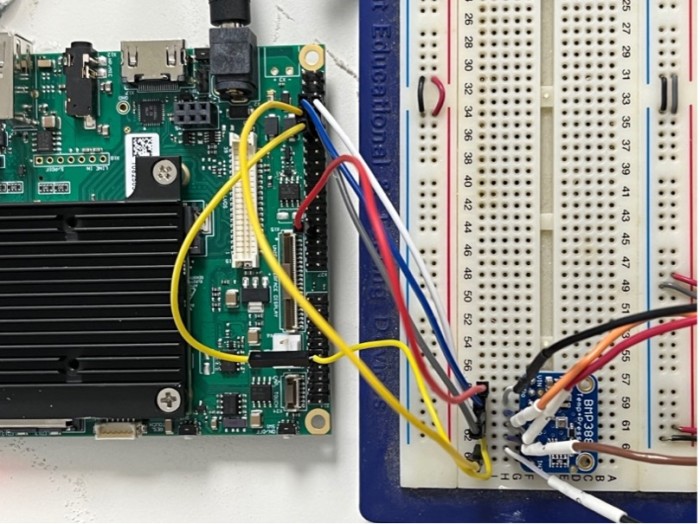
The above will result in the following connections (we can also see the connections to the logic analyzer on the right):
Now that we have the appropriate kernel and device tree modifications in place, we can focus on implementing the application that will use spidev to communicate with the Bosch BMP388 pressure sensor. We can use the following implementation as a reference: (https://github.com/mabembedded/spidev-test/blob/main/spidev-test.c). In “main”, the first thing we do is to open the file that represents the spidev interface:
spidev_fd = open(device, O_RDWR);
Then, we set the relevant SPI parameters, such as bits per word and the maximum clock speed, using the “ioctl” interface into the spidev driver (a detailed review of the ioctl driver interface will be covered in another blog post):
ret = ioctl(spidev_fd, SPI_IOC_WR_BITS_PER_WORD, &bits);
.
.
.
ret = ioctl(spidev_fd, SPI_IOC_WR_MAX_SPEED_HZ, &speed);
SPI controllers use the bits per word parameter to specify how many cycles the SPI clock will be active until there is a pause. A greater bits per-word parameter improves performance (since more bits can be pushed without additional pauses). For now, we will set this parameter to 8.
Of course, the max speed is how fast in time the SPI clock can be pulsed (along with the data coming out of the MOSI and MISO lines). In the example implementation, we have set the parameter to 500 kHz. Again, increasing this value will improve performance, but the maximum value depends on the SPI controllers on the host and device sides.
The crux of the implementation occurs in the “spi_transfer” function. Before we review the function itself, let’s discuss our strategy and review the datasheet. A personal best practice that I use in implementing applications that interface with a new peripheral is to first review the datasheet. Then, I determine if the device has a register that I can query that will always give me the same value, which is usually an identification register. This allows me to focus my attention solely on the implementation of the software interface to the peripheral. Another personal best practice is to always have my logic analyzer handy to get insight into the data that’s transferred on the wire.
The two relevant sections of the datasheet of any peripheral that we need to review before implementing a solution are the register map and the interface sections. The register map helps us follow the first personal best practice outlined above. The interface section (coupled with our logic analyzer) will help us ensure that our implementation is correct.
In the BMP388 datasheet, the CHIP ID register is a great candidate to test our implementation:
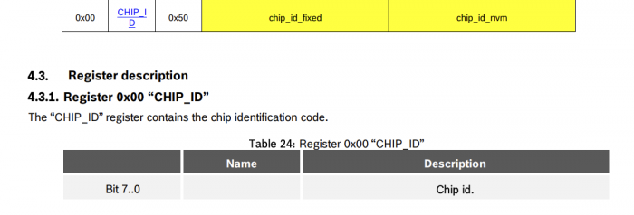
This register, at offset 0x00, will always return a value of 0x50.
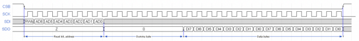
Section 5.3, which describes the SPI interface, has two important pieces of information. First, even though each register address is 8 bits, the most significant bit (MSB) will be used to instruct the device whether we will read from or write to that register:
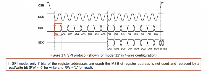
Second, the section tells us that when we want to perform a read, we must first transmit the register address (with the MSB set to a ‘1’ for a read) and then send two dummy bytes. The first dummy byte will return all zeroes on the MISO line, and the second dummy byte will return the data contained in the register:
Now, let’s look at the implementation of the spi_transfer function. First, we create two arrays. The first array contains the data we will transmit to the pressure sensor over the SPI bus. The second array will contain the response.
uint8_t tx[] = { 0x80, 0xff, 0xff };
uint8_t rx[3] = { 0xaa, 0xbb, 0xcc };
Again, from the SPI read diagram from the datasheet, we see that we need to send three bytes. The first byte contains the address of the CHIP ID register (with the MSB set to indicate a read), which results in a value of 0x80. The two remaining bytes are the dummy bytes.
Then, we populate the appropriate data structure with the relevant pieces of information that we will send to the spidev driver:
struct spi_ioc_transfer tr = {
        .tx_buf = (unsigned long) tx,
        .rx_buf = (unsigned long) rx,
        .len = 3,
        .speed_hz = speed,
        .bits_per_word = bits,
};
The “tx_buf” element of the data structure needs to be set to the array with the data sent over the MOSI line. The “rx_buf” element needs to be set to the array that will ultimately contain data received on the MISO line. The “len” element needs to be set to 3 since we send 3 bytes. Finally, the “speed_hz” element needs to be set to the maximum SPI clock we specified earlier, and similarly for the “bits_per_word” element.
Running the Application
If we compile and run the application on our Apalis Ixora board, we can see the following output:
apalis-imx8-07039790:~$ ./spidev-test
Bits per word: 8
max speed: 500000 Hz (500 KHz)
ff ff 50
We can see that we received the expected value of (hex) 50 by reading the CHIP ID register! For additional confirmation, we can view the data exchange on our logic analyzer:
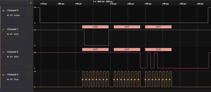
In summary, spidev is a great framework for an application that interfaces with an SPI peripheral on an embedded Linux solution. In this blog post, we showed how to make a few minor adjustments to the Linux kernel and appropriate device tree to enable this framework on our system. We also learned about some personal best practices that have worked well when testing solutions against real hardware. Finally, we showed important sections of a sample implementation in C. We demonstrated the output not of the application but also of logic analyzer traces that were used to capture the relevant SPI lines.


- Comments
- Write a Comment Select to add a comment
To post reply to a comment, click on the 'reply' button attached to each comment. To post a new comment (not a reply to a comment) check out the 'Write a Comment' tab at the top of the comments.
Please login (on the right) if you already have an account on this platform.
Otherwise, please use this form to register (free) an join one of the largest online community for Electrical/Embedded/DSP/FPGA/ML engineers:

