


Arduino robotics #4 - HC-SR04 ultrasonic sensor
Arduino Robotics
Arduino robotics is a series of article chronicling my first autonomous robot build, Clusterbot. This build is meant to be affordable, relatively easy and instructive. The total cost of the build is around $50.
1. Arduino robotics - motor control
2. Arduino robotics - chassis, locomotion and power
3. Arduino robotics - wiring, coding and a test run
4. Arduino robotics - HC-SR04 ultrasonic sensor
What is a robot?
There are many different definitions for the word robot. My personal opinion is that for a machine to be considered a robot, it needs to be able to sense and react to a dynamic environment, with little or no human intervention. Based on this definition, Clusterbot is still a machine - now we are going to turn him into a robot.
Ultrasonic Sensors
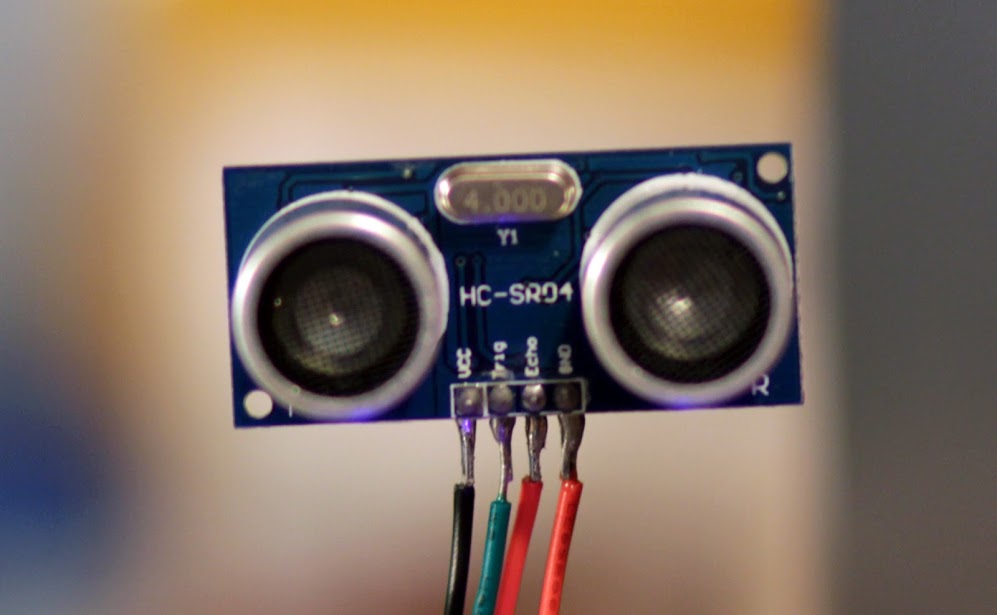
I decided to go with the HC-SR04 Ultrasonic sensor. Functionally, the HC-SR04 is roughly the same as the Parallax PING sensor. These sensors emit a 40KHz pulse when an input is provided to the trigger pin. The sensor measures the amount of time it takes for the 40KHz signal to come back, then outputs a variable-width pulse proportional to the time measured. In the case of the Parallax PING, the trigger and return pulse share the same pin. On the HC-SR04, the trigger and echo pins are separate.
The HC-SR04 sensors are about $3 shipped on eBay. Parallax PING sensors are $29.99. I've never used the PING sensor, but I've used several of the HC-SR04's. The only complaint I have is the maximum range. The published range of the HC-SR04 is 450cm. I've been able to achieve consistent and accurate results out to 100 cm (about 3.5 feet). Talking to a few others on Google+, 100cm seems to be the typical range. If maximum distance is important, the PING has a published range of 300cm.
Using the HC-SR04 Ultrasonic sensor
Using the HC-SR04 sensor is pretty simple once you install the required library to the Arduino IDE. The library I used is available for download here: HC-SR04 Arduino Library. You may also find this info from Arduino.cc useful: how to add libaries to the Arduino IDE.
Here's a simple bit of Arduino code to test the HC-SR04 sensor. Output will be to the serial monitor in the Arduino IDE. Make the following connections on your Arduino and HC-SR04:
- 5V on Arduino to VCC of HC-SR04
- Digital pin 12 of Arduino to TRIG of HC-SR04
- Digital pin 13 of Arduino to ECHO of HC-SR04
- GND of Arduino to GND of HC-SR04
Now upload the following code to the Arduino:
#include<Ultrasonic.h>  /*include user installed library*/
Ultrasonic ultrasonic(12,13);  /*create instance of ultrasonic and define pins*/
void setup() {
Serial.begin(9600);  /*begin serial port comm at 9600 bps */
}
void loop()
{
  Serial.print(ultrasonic.Ranging(INC));  /* INC for inches, CM for centimeters */
  Serial.println("in");
  delay(100);
}
Once the code is uploaded, you can open the serial monitor on the Arduino IDE on your computer. You should see the distance the ultrasonic sensor is measuring, updated 10 times per second.
Adding the HC-SR04 to Clusterbot
Now we are going to add the HC-SR04 to Clusterbot. Also adding an LED and a Speaker for fun.
- 5v on Arduino to VCC of HC-SR04
- Pin 10 of Arduino to TRIG of HC-SR04
- Pin 11 of Arduino to ECHO of HC-SR04
- GND of Arduino to GND of HC-SR04
- Pin 7 to an LED
- Pin 9 to a Speaker
The Code
#include<Ultrasonic.h>
Ultrasonic ultrasonic( 10, 11);

#define PWMA 3
#define AIN1 0
#define AIN2 1
#define PWMB 5
#define BIN1 2
#define BIN2 4
#define STBY 6
#define LED 7
#define SPEAKER 9
#define FREQ 1000

void setup() {
pinMode(PWMA,OUTPUT);
pinMode(AIN1,OUTPUT);
pinMode(AIN2,OUTPUT);
pinMode(PWMB,OUTPUT);
pinMode(BIN1,OUTPUT);
pinMode(BIN2,OUTPUT);
pinMode(STBY,OUTPUT);
pinMode(LED,OUTPUT);
}

void loop() {
  startUp();
  while(ultrasonic.Ranging(INC) < 9) {
    rotateLeft();
    digitalWrite(LED,HIGH);
    tone(SPEAKER,FREQ);
    delay(20);
    digitalWrite(LED,LOW);
    noTone(SPEAKER);
    delay(20);
  }
  goForward();
  digitalWrite(LED,HIGH);
}

void goForward ()
{
  digitalWrite (AIN1,HIGH);
  digitalWrite (AIN2,LOW);
  analogWrite(PWMA,233);
  digitalWrite (BIN1,HIGH);
  digitalWrite (BIN2,LOW);
  analogWrite(PWMB,255);
}

void rotateLeft ()
{
  digitalWrite (AIN1,LOW);
  digitalWrite (AIN2,HIGH);
  analogWrite(PWMA,255);
  digitalWrite (BIN1,HIGH);
  digitalWrite (BIN2,LOW);
  analogWrite(PWMB,255);
}

void startUp ()
{
  digitalWrite(STBY,HIGH);
}
The test run!
Hotwash
The test run was a success! I especially liked how well Clusterbot performed when completely surrounded. He continued to spin on his axis until I gave him a way out, which he took at the first opportunity. I kept the test code really simple - either turn left or go forward. I've found it's important to keep a system as simple as possible when adding a new component. Adding to much to a system at once makes it more difficult to troubleshoot the entire system when things don't go as planned.
Errata
There are a few things I would do differently if I were building Clusterbot now:
- I would use the 6V motors here instead of the 3V Mabuchi motors. The 6V motors have a lower current draw, and operate at a voltage that is in the "sweet spot" for the TB6612FNG motor driver.
- I would make a two-layer round platform out of a light plywood. Bottom level for drivetrain and batteries, top level for electronics.
- I would use diodes to avoid EMF
- I would use the New Ping library for the HC-SR04. It wasn't available when I originally built Clusterbot, but looks like it is really good. I especially like the ping.median(iterations) function - the occasional spurious data can be rejected that way.


- Comments
- Write a Comment Select to add a comment
ie where must pwma be connected and others
To post reply to a comment, click on the 'reply' button attached to each comment. To post a new comment (not a reply to a comment) check out the 'Write a Comment' tab at the top of the comments.
Please login (on the right) if you already have an account on this platform.
Otherwise, please use this form to register (free) an join one of the largest online community for Electrical/Embedded/DSP/FPGA/ML engineers:


