


Arduino robotics #3 - wiring, coding and a test run
Arduino Robotics
Arduino robotics is a series of article chronicling my first autonomous robot build, Clusterbot. This build is meant to be affordable, relatively easy and instructive. The total cost of the build is around $50.
1. Arduino robotics - motor control
2. Arduino robotics - chassis, locomotion and power
3. Arduino robotics - wiring, coding and a test run
4. Arduino robotics - HC-SR04 ultrasonic sensor
Connections
Use the chart below as a reference for making connections between the Arduino, TB6612FNG motor driver, motors and battery packs. I remember that the wires from my 3V battery pack were too thin to connect to the breadboard. I resolved this by tinning the end of the wire with a bit of solder. You can either do this, solder pins to the wires, or replace the flimsy wire with proper hookup wire.
| Arduino Uno | TB6612FNG | Motor A | Motor B | 3V battery pack | 9V battery pack |
| GND | GND | ||||
| 5V | VCC | ||||
| AO1 | - pole | ||||
| AO2 | + pole | ||||
| BO2 | + pole | ||||
| BO1 | - pole | ||||
| VMOT | + pole | ||||
| GND | - pole | ||||
| 3 | PWMA | ||||
| 1 | AIN2 | ||||
| 0 | AIN1 | ||||
| 6 | STBY | ||||
| 2 | BIN1 | ||||
| 4 | BIN2 | ||||
| 5 | PWMB | ||||
| GND | GND | ||||
| Barrel conn | Barrel conn |
The Code
Now we can test the basic functionality of Clusterbot, we just need to write a little code first. I've decided to make a function for each basic type of movement to keep main as clean as possible.
I'll provide this logic table, derived from the TB6612FNG datasheet, as reference. It defines how we make the motors spin in the direction and speed that we want.
| IN1 | IN2 | PWM | STBY | MODE |
| H | H | H/L | H | Short Brake |
| L | H | H | H | CCW |
| L | H | L | H | Short Brake |
| H | L | H | H | CW |
| H | L | L | H | Short Brake |
| L | L | H | H | Stop |
| H/L | H/L | H/L | L | Standby |
/* Define pinout of Arduino to match physical connections */
#define PWMA 3
#define AIN1 0
#define AIN2 1
#define PWMB 5
#define BIN1 2
#define BIN2 4
#define STBY 6

void setup() {

/* Define all 7 pins as outputs to the TB6612FNG driver */
pinMode(PWMA,OUTPUT);
pinMode(AIN1,OUTPUT);
pinMode(AIN2,OUTPUT);
pinMode(PWMB,OUTPUT);
pinMode(BIN1,OUTPUT);
pinMode(BIN2,OUTPUT);
pinMode(STBY,OUTPUT);

}

void loop() {

  startUp();
  goForward();
  delay(5500);
  turnAround();
  goForward();
  delay(5500);
  turnAround();
  goBackward();
  delay(5500);
  rotateLeft();
  delay(560);
  rotateRight();
  delay(560);
  goForward();
  delay(3000);
  applyBrakes();
  delay(2000);
  }

/* Function definitions */
/* Due to variations in motor output, it was found that */
/* a duty cycle of 233 on the left motor and 255 on the */
/* right motor is necessary for approximately straight  */
/* line, full speed travel                              */
/* Testing revealed Clusterbot will do 27 rotations per */
/* minute, with motors turning in opposite direction at */
/* full duty cycle.  This "constant" was used to        */
/* determine the length of time to turn to make 90, 180,*/
/* and 360 degree turns.                                */

void goForward ()
{
  digitalWrite (AIN1,HIGH);
  digitalWrite (AIN2,LOW);
  analogWrite(PWMA,234);
  digitalWrite (BIN1,HIGH);
  digitalWrite (BIN2,LOW);
  analogWrite(PWMB,255);
}

void goBackward ()
{
  digitalWrite (AIN1,LOW);
  digitalWrite (AIN2,HIGH);
  analogWrite(PWMA,233);
  digitalWrite (BIN1,LOW);
  digitalWrite (BIN2,HIGH);
  analogWrite(PWMB,255);
}

void rotateRight ()
{
  digitalWrite (AIN1,HIGH);
  digitalWrite (AIN2,LOW);
  analogWrite(PWMA,255);
  digitalWrite (BIN1,LOW);
  digitalWrite (BIN2,HIGH);
  analogWrite(PWMB,255);
}

void rotateLeft ()
{
  digitalWrite (AIN1,LOW);
  digitalWrite (AIN2,HIGH);
  analogWrite(PWMA,255);
  digitalWrite (BIN1,HIGH);
  digitalWrite (BIN2,LOW);
  analogWrite(PWMB,255);
}

void veerLeft ()
{
  digitalWrite (AIN1,HIGH);
  digitalWrite (AIN2,LOW);
  analogWrite(PWMA,190);
  digitalWrite (BIN1,HIGH);
  digitalWrite (BIN2,LOW);
  analogWrite(PWMB,255);
}

void veerRight ()
{
  digitalWrite (AIN1,HIGH);
  digitalWrite (AIN2,LOW);
  analogWrite(PWMA,255);
  digitalWrite (BIN1,HIGH);
  digitalWrite (BIN2,LOW);
  analogWrite(PWMB,190);
}

void applyBrakes ()
{
  digitalWrite (AIN1,HIGH);
  digitalWrite (AIN2,HIGH);
  analogWrite(PWMA,255);
  digitalWrite (BIN1,HIGH);
  digitalWrite (BIN2,HIGH);
  analogWrite(PWMB,255);
}

void startUp ()
{
  digitalWrite(STBY,HIGH);
}

void turnAround()
{
  rotateLeft();
  delay(1370);
}

void shutDown ()
{
  digitalWrite(STBY,LOW);
}
The test run!
The time has come to see what Clusterbot can do. He's deaf and blind, but he's got a few moves. Let's watch:
So, Clusterbot can move! Now it's time to give Clusterbot vision and maybe a voice. Before that, there's one more thing to take care of:
The Makeover
Clusterbot has quite a few jumper wires, and I've found I can hardly pick him up without accidentally pulling one of the jumpers out. It's a real mess, it's time to clean things up a bit. I substitute sloppy jumper wires for hookup wire cut to the proper length and pressed flat.
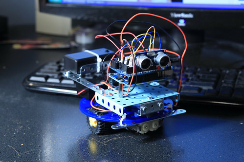
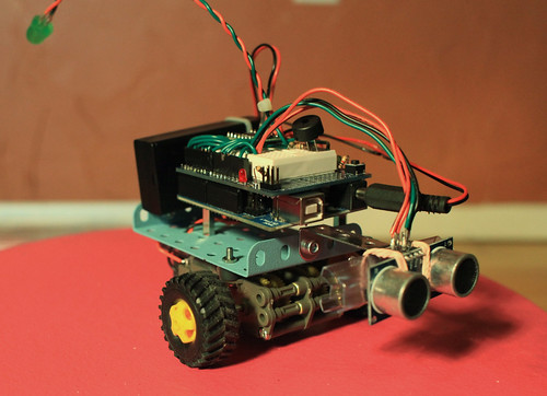
I also decide that the acrylic base isn't really doing anything for Clusterbot. I mount the caster directly to the bottom of the gearbox, and mount the erector-set frame to the top. Much cleaner! Here's the before and afters:
Next time
We'll add a sensor and a few other gadgets, and let Clusterbot start making a few decisions for himself.


- Comments
- Write a Comment Select to add a comment
To post reply to a comment, click on the 'reply' button attached to each comment. To post a new comment (not a reply to a comment) check out the 'Write a Comment' tab at the top of the comments.
Please login (on the right) if you already have an account on this platform.
Otherwise, please use this form to register (free) an join one of the largest online community for Electrical/Embedded/DSP/FPGA/ML engineers:


