


A Useful Current Profiling Method
In one of my recent projects, I had to capture the dynamic current profile of a short-range wireless embedded platform for a number of operation scenarios. Due to the dynamic nature of the current consumption involved, I was unable to use a standard voltmeter for this job. On the time axis, I needed a minimum resolution of 1 millisecond and the accuracy of the current measurement was supposed to be better than 2 mA. This task would be a piece of cake with a Digital Storage Oscilloscope, which I did not have at the time and therefore I had to come up with a cheaper method to get the job done.
The top-level diagram of the solution I came up with is shown below. I used 3.0 V button cell battery as my power source in all of my measurements, however you can use an ordinary DC power supply in your measurements as required by the particular load you use. The load is the device whose current profile we are interested in. The load’s positive terminal is connected to the battery and the ground terminal is in series with a 0.3 ohm shunt resistor (Rs) that is terminated at ground. The shunt resistor needs to have a small value in order not to cause a large voltage drop across the Rs, which decreases the required operational voltage across the load (You can think of Rs as an ordinary wire with a bit of resistance). The power of Rs is usually a high value (e.g. 1 Watt) in order not to get damaged by the current flowing through it. The voltage across the shunt resistor (denoted Vs) varies depending on the current drawn by the load. This current is simply equal to Vs/0.3 amperes.

Note that Vs is typically small due to the small value of the shunt resistor. Therefore, digitisation and the measurement of Vs directly is difficult and an intermediate amplification stage is necessary. In my application, an amplifier with a gain of ~11 was used. If you need higher gains in your measurements, simply adjust the R2/R1 ratio as needed. The overall gain for the amplifier topology provided is ( 1 + [R2/R1] ). I simply used a general-purpose LM324 opamp which worked really well.
The output of the amplifier is fed to an analog-to-digital converter (ADC) that had a resolution of 10 bits per sample and ran at a sampling frequency of 20 kHz. This sampling rate equates to 50 microseconds between successive samples, which is better than what I needed. Higher sampling rates can provide much better resolution in time but remember that your storage requirements will also increase as a result. The digital output of the ADC is converted to milliamps and for each sample a time stamp in milliseconds is also associated. Note that the blocks indicated inside the dotted lines are an integral part of the microcontroller platform (i.e. AtMega2560) I used in my application.
In my application, I dumped the SRAM content after each measurement session due to the memory limitations of the platform I used. However, I also experimented with real-time serial dump of each ADC sample and that method will also work if your measurement resolution requirements are more relaxed. You can easily use a serial terminal program such as TeraTerm to save the ADC samples.
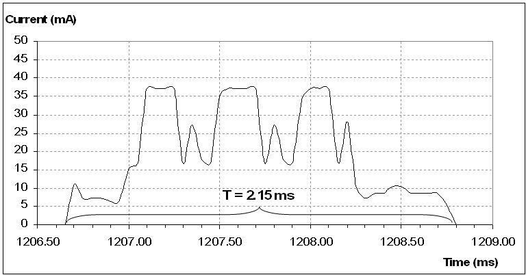
Using the above set up, it is possible to sample current levels as low as 1.15 mA. Figure below illustrates a captured current profile during the RF transmission of the load I used in my project. The repetitive transmission tasks can easily be identified using the dynamic current profile as shown in the figure.
I hope you will find my tried and tested method for current measurement useful in your projects. The best part of it is it allows you to get accurate measurements without an expensive digital storage oscilloscope!


- Comments
- Write a Comment Select to add a comment


To post reply to a comment, click on the 'reply' button attached to each comment. To post a new comment (not a reply to a comment) check out the 'Write a Comment' tab at the top of the comments.
Please login (on the right) if you already have an account on this platform.
Otherwise, please use this form to register (free) an join one of the largest online community for Electrical/Embedded/DSP/FPGA/ML engineers:


