


Dealing With Fixed Point Fractions
Fixed point fractional representation always gives me a headache because I screw it up the first time I try to implement an algorithm. The difference between integer operations and fractional operations is in the overflow. If the representation fits in the fixed point result, you can not tell the difference between fixed point integer and fixed point fractions. When integers overflow, they lose data off the most significant bits. When fractions overflow, they lose data off the least significant bits. When you do it correctly anyway.
In "A Fixed-Point Introduction by Example" , Christopher Felton describes fixed point representation. Another common way to describe fixed point is with Q notation. Q4.12 means 4 bits before the binary point and 12 bits after the binary point. Typically I prefer to use very few bits before the binary point so that all values are scaled to be in the range $<\pm1$. The advantage of this is that I can (usually) keep track of the scaling.
For example, if I have a $10$ bit ADC and I use an FIR filter to pick out some frequency band I might use a set of $16$ bit coefficients. I can assume my ADC values are in the range $<\pm 1$. All my coefficients are also in the range $\pm 1$. But when I perform the multiply, the result will be in the range $\pm \frac{1}{2}$. Because I'm using fixed point, I will lose precision if I don't do a left shift after the multiply.
Another way to look at this is by noting both values have sign bits. If I multiply a signed Q2.14 with a signed Q4.12 my result is Q6.26 with two sign bits. So my useful result is really Q5.26. If I multiply an unsigned Q2.14 with a signed Q4.12 then my useful result is Q6.26. This is where I start running into trouble - I perform a shift when I should not have.
Performing the shift does not increase precision, it just helps maintain it. The transformation is from Q6.26 with 2 sign bits to Q5.27 with 1 sign bit and the least significant bit is zero. But it is not necessary if I keep track of where the scaling is all the way through the algorithm.
The following diagram shows one way to think about an FIR or similar algorithm where data is combined by multiplication and addition. The 10 bit data is assumed to be in the range $<\pm 1$. Note that it is always less than exactly $+1$ by one least significant bit, but $-1$ can be represented since it is just the sign bit.. The coefficients are scaled to be in the same range so that the $26$ bit result is known to have 2 sign bits.
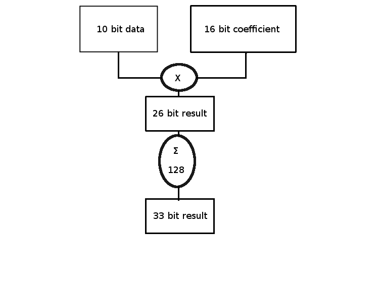
If the number of terms added is greater than $64$ and less than $128$ the worst case growth of the result is $7$ bits. If we get all $-1$ on our input data and then assume the coefficients are $+1$, the result would be $-127$. Our Q10 times Q16 gives Q26 and then summing these close to $128$ times gives us Q7.26 for the result.
We know that at least two of the most significant bits are sign bits. But chances are there are a lot more sign bits than that. More typically the average should be zero over many runs - we intuitively expect this because the input signal will be averaging around $0$ and typical coefficients are symmetric. But if we don't account for worst possible case, our system will fail.
There are several ways to deal with the process. One is to keep all the bits all the way through. For complex systems with multiple filters or algorithms this is going to consume a lot of resources. Another is to shift when needed. The problem with this is that you have to keep track of how many shifts you really did so you know the scale at the end. It is almost floating point. The advantage is that the result has the best accuracy.
The simplest way is to perform shifts after every operation so the result is in the range $\pm 1$. Typically this isn't so much shifting as it is chopping bits off the low end. In the summation we can perform a right shift after every addition. The following diagram is a poor representation of multiple operations in time to illustrate the idea.
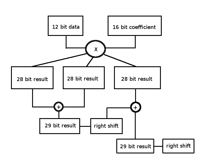
This definitely hurts overall precision. In this example we start with 12 bit data and we are keeping 28 bit results. This is more than enough accuracy. In fact it is probably overkill. We really only need to keep 20 bit results after the multiply, do all the sums with shifts and then keep a 16 bit final result. Since our source data is only 12 bits that's all we really can hope for.
Most FPGA's have $9$ bit memory width so typical results should be chopped to a multiple of $9$ bits. The example above can run data through at $27$ bits just as well as $28$ since we know the most significant bit is a duplicate of the sign bit anyway. Even if the ADC produces unsigned values then the top $27$ bits are what we keep after the multiply.
When laying out fixed point algorithms after testing them in floating point it's a really good idea to make sure the scale stays in a reasonable range. You can use the floating point intermediate results to compare with your estimates of what values you should have at any point in your fixed point algorithm. If your floating point test is in the range $10^{-3}$ (around $2^{-10}$) and your fixed point algorithm has gone to zero, you know are not keeping track of shifts correctly.
It always takes me a few tries to get fixed point fraction algorithms to run smoothly. Usually I miss sign bits or forget I changed the summation depth and get integer overflow results when I meant to keep track of just the fractional part. It is not hard, but the details really matter. Using Q notation typically helps me find where I went wrong.
There is no "right way" to ensure your algorithm works. There are an infinite number of wrong ways, and I'm sure I have not found them all. But with a little care, a fast and efficient fixed point algorithm can do the job with fewer resources on your next project.


- Comments
- Write a Comment Select to add a comment

Software engineers tend to use fractional values while HDL engineers tend to think of data as integers directly. The HDL engineer will think of scaling in relation to how many LSB bits are truncated off a result.
Kaz

There is a comparatively new IEEE.Fixed_pkg package in VHDL, which deals with the fixed numbers strictly. It is more complex that its parent NUMERIC_STD. Therefore, this standard is used rarely.
But it resolves many mistakes in bitwidth, and point matching in the signal assignments. The digit numeration of the bit vectors becomes more natural and clear like in Q notation.
To post reply to a comment, click on the 'reply' button attached to each comment. To post a new comment (not a reply to a comment) check out the 'Write a Comment' tab at the top of the comments.
Please login (on the right) if you already have an account on this platform.
Otherwise, please use this form to register (free) an join one of the largest online community for Electrical/Embedded/DSP/FPGA/ML engineers:


