


Using IR Photodiode as a sensor
I am a student working on a project with MSP-EXP430F5438 LaunchPad and I'm trying to use IR photodiode to open a gate in a model of a parking lot. In order to check my circuit I wrote a simple code just to check if the photodiode connection is working. Code purpose is to turn on the launchpad's LED.
This is my code:
void main (void)
{
// Port1 - IR detectors (located in RF3 )
P1DIR = 0x03; // configure pin P1.0 & P1.1 for led output
P1OUT = 0x00; // clear the output of P1
P1SEL = 0x00; // set all port1 pins as I/O
//Port5
P5DIR = 0x00; // P5.0 IR input
P5SEL = 0x00; // set all P5 pins as I/O
P5OUT = 0x00;
while(1){
if(P5IN & 0x01)
P1OUT = 0x03;
else
P1OUT = 0x00;
}
}
also, I am using 10Kohm resistor before the port input as a pullup resistor
Nothing happens in the LEDs of the MSP and also when I debug the program I don't see the input changing
I've checked my circuit bu connecting a simple LED instead of the port and I see it toggles when I block the IR LED <-> IR PhotoDiode lien of sight
any ideas what I'm doing worng?
Thank you
** SEE MY OTHER REPLY, I THINK THAT WILL FIX IT **
I've used the MSP430 a little bit in the past, but not much.
I have always put the PxSEL configuration before any PxDIR - but I'm not sure if that will have any effect, but it selects the GPIO functionality, before setting any GPIO bits.
Also, I'd be tempted to change P5OUT = 0x00; to P5OUT = 0x01; in order to ensure the input isn't being driven low internally (again, not sure if this will be an issue, but it's normally good practice to drive all input pins high when possible).
Wait a minute... if a 1 in the PxDIR register makes that pin an output, then P5DIR should be 0x00 not 0x01 - your input pin, is being configured as an output!
**EDIT** TYPO.
Embarrassing mistake. I copied the wrong code. Anyway, even when P5DIR = 0x00 it didn't work

Disregard my earlier comment. I think SpiderKenny is correct.
I've used MSP430 uCs a lot although not the one you're using. One question - what resistor are you using to limit the current going into the LED?
560[Ohms]
Like I wrote in the original post, I tested the circuit just to make toggle a LED and it is working. I also measured current and voltage using a DMM and everything seems ok
This is my circuit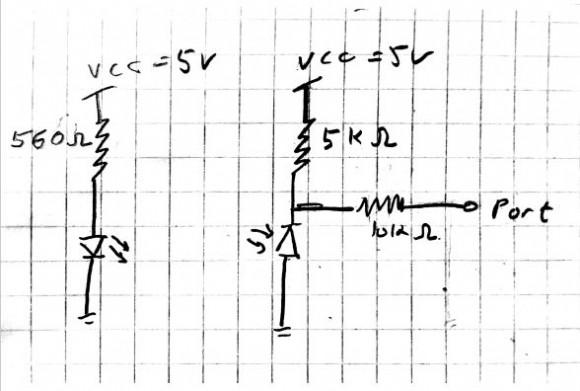
Isn't your MSP430 running off 3.3V? If so, change VCC to 3.3V. I don't think that will solve your problem but you risk destroying input and output ports by connecting things to voltages beyond the absolute maximum rating.
Thought about it.
1. That's what our lab guide told us to do, I know it's strange but still
2. I changed it to 3.3V and like you said it didn't help
Do you have another Launchpad board you could use? I've had port pins blown out, probably from static charge that I had when I was handling them. If no other Launchpad is available, you might try wiring to different output pins if there are unused pins available.
already tried different pins and different launchpads
Thank you for your help!
Did that fix it?
sorry, it didn't
Perhaps this is it - as I understand it, you want to turn on a visible LED (on the Launchpad board) whenever your photodiode sees the output of an infrared LED (driven by a second output on the Launchpad board).
However, I believe there's an error in your setup. You never turn on the infrared LED unless the photodiode sees infrared light. But your photodiode will never see infrared light since the infrared LED never turns on until after the photodiode sees light. Does that make sense?
So what I'm saying is that your infrared LED needs to be on all the time (just like your "test" LED was on all the time).
I think I explained myself the wrong way. True, I'm trying to turn on a visible LED on the launchpad, using a "switch" made with an infrared photodiode.
But, the IR LED and the photodiode circuit is a seperate circuit which is driven by a separate 5V VCC input and the voltage is being read by the MSP's input port

1)I assume they both share the same Ground between the different power sources.
'
2)Your drawing indicates the ir receiver is wired..
the internet shows both positions - cathode down and anode down.
My learning is the cathode is down.
your pullup is 5K - that means only 1ma will flow through the
ir receiver.
3) Is the IR receiver from a modulated device?? like a receiver
module from a remote control setup? - those have a built in demodulator, but they also have 3 pins !!!
1) True
2) True, why is that a problem?
3) it's a photodiode, not a special reciever. When it gets IR light it will conduct, but it needs to be reversed biased in order to do it

Consider going back a pace and ripping out the sensor code and just trying to make the LED blink with a timing loop. I'd use something boneheaded like:
while(1)
{
(Turn LED on)
for (volatile int n = 0; n < 10000; ++n);
(Turn LED off)
for (volatile int n = 0; n < 10000; ++n);
}
If you don't get blinky, you'll know it's not your sensor that's at fault.
It is blinking, and like I said I also checked the sensor and it's working
Definitely a problem with the input,then. I'd verify that the pin is actually getting pulled to the correct voltages. Then I'd double-check that I had all the right bits set. It gets very tedious getting a foothold with a new processor, sometimes.
Not sure I understood what you meant here - "I'd verify that the pin is actually getting pulled to the correct voltages"
Can you explain?
Did you mean measure the voltage drop on the 10k resistor?
How can I measure the pin's voltage?
With a voltmeter. Put the negative lead on the board's ground, and the positive lead on the pin in question. Unless you suspect that the board is faulty, you can use the header pin that you're wiring to.
If you don't have a voltmeter available, decent basic ones are available for $10 or $15 on eBay, or possibly even still from Radio Shack. Search on "Multimeter".
What voltages do you read on your input pin (P5.0) when the IR photo diode is illuminated and not illuminated? Check the data sheet to make sure the voltage levels meet the '0' and '1' thresholds.
On your board do you have any control commands? Remember the MSP430 uses a single address range for memory and peripherals. (At least this was the case when I used the 430) So if you can read memory you can check the IO port registers. So read the P5 IN register and check you the IR input pin value corresponds to the IR diode illuminated or not.
Don't forget, as already mentioned, if you inherited the board from someone else the input pin may be blown.
Also check your dev board's circuit and make sure there is nothing significant between your 10 k resistor and the actual pin on the chip. Also check the connection you are using on the dev board is the right one for P5.0.
Again as already mentioned try using P5.0 as an output and make sure the voltage on your 10 k resistor toggles with the P5OUT register bit 0 value. This will confirm the 10 k resistor really is connected to P5.0.
As you expand your code you may well want to use other IO pins. So I suggest you only change the port register bits you are interested in. Use a read / modify approach to leave other pins alone. EG
P1DIR |= 0x03; /* To set the bit for pins 0 & 1 */
P1DIR &= ~0x03; /* To clear the bit for pins 0 & 1 */
Best of luck.
Problem solved. I didn't connect the grounds of the circuit and the MSP board
Newbie mistake


