


Recently I was faced with a dilemma while working from home. I needed to verify an implementation of first-order sigma-delta modulation used to adjust LED brightness. (I have described this in more detail in Modulation Alternatives for the Software Engineer.) I did not, however, have an oscilloscope.
And then I remembered something, about a technique called “light painting”: basically a long-exposure photograph where a light source is moved during the time the shutter is open. I’d first seen this in a magazine article about some unusual photographs, including Eric Staller‘s 1979 work, Hydrascope. (I wish I could remember the magazine! The article was likely from Games Magazine or National Geographic, circa 1983-1986.)

Staller created it by walking through a passageway at night, with two strings of Christmas light bulbs mounted in a circular and a diamond shape, leaving glowing trails behind him. The artist is therefore in the painting as well, but so dim and smeared that he was rendered effectively invisible.
Technically, all photographs are light paintings; light falls on a photosensitive plate or film or sensor, causing a chemical or electrical change as the light energy builds up in different parts of the image.
It has been used, fairly early on, as a method of quantitative measurement: see for example Eadweard Muybridge’s 1878 series of twelve carefully-timed photographs of a horse trotting or the physiological studies of Étienne-Jules Marey and Georges Demeny starting in the 1880s.

Nothing new under the sun.
Cathode ray tubes painted with light for decades during the 20th century, taking off in the 1930s and dominating the display market before being overtaken by LCD flat-panel displays somewhere around 2003-2005. The principle behind the CRT is to shoot a beam of electrons towards a phosphor-covered screen, steering the beam with electromagnets so it can scan across the CRT screen. They were used, of course, by televisions and computer monitors — and oscilloscopes (also in the 1930s), where input voltage signals controlled the horizontal and vertical positions of the electon beam. Use a linearly-sweeping horizontal input, and the signal of interest for the vertical input, and you can visualize a waveform directly.
As I said, I don’t have an oscilloscope at home. But I do have a digital camera, and I figured I could take a picture of my sigma-delta-modulated LED, moving the camera smoothly enough so that the LED dot scanned across the image.
The results are shown below. It’s pretty difficult to synchronize moving the camera at the same time you press the shutter release, but if I tried it enough, I found I could get at least one or two good photographs.
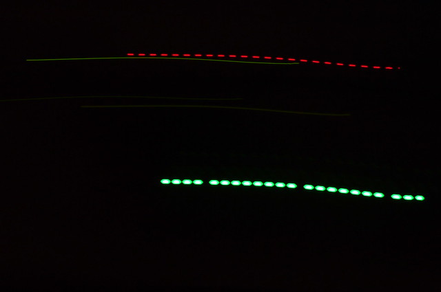
Here is one with p=2048, q=4096, exposure of 1/10 second, with the tick rate (aka “chip rate”) at 500Hz, so nominally there should be 50 bit samples within the photograph. If you look carefully at the green blinking LED, you will notice 24 points of light with 23 gaps between them, showing somewhere between 47 and 49 bit samples. (We don’t know whether the photograph started and ended with the green LED on, or off.) Not bad, at least it’s consistent.

Since I have a camera with a mechanical shutter, and a circuit board with a quartz crystal, I’m inclined to believe the LED timing is more exact, and the exposure is more likely around 96 msec rather than the nominal 100 msec.
The red LED is a communications LED not under my control, but most likely it’s also blinking on and off around 500Hz.
The green LED is much brighter; too bright, in fact, and I think it’s causing nonlinearities in my camera’s image response. The green “blobs” aren’t out-of-focus artifacts.
At any rate, next is p=2176, q=4096 (p/q = 17/32), exposure of 1/10 second.

Here the green LED is showing the following bit sequence (1 = on, 0 = off):
1010101101010101010101101010101010101011010101
Is this correct?
observed_sequence = '1010101101010101010101101010101010101011010101'

def sigmadelta(p,q,accum_init=0):
    accum = accum_init
    while True:
        accum += p
        if accum >= q:
            out = 1
            accum -= q
        else:
            out = 0
        yield out

def sdsequence(p,q,accum_init,n=46,off='0',on='1'):
    sequence = ''
    for k,out in enumerate(sigmadelta(p,q,accum_init)):
        if k >= n:
            break
        sequence += '1' if out == 1 else '0'
    return sequence

print repr(observed_sequence)
sdsequence(2176,4096,3270)
'1010101101010101010101101010101010101011010101'
'1010101101010101010101101010101010101011010101'
It is! It surprised me at first to see that the number of single 1 pulses between the double 1 pulses is different, alternating between 6 and 7 single 1 pulses, but that’s just the way the math works out.
Here’s a third photo with p=1920, q=4096, 1/10 second exposure:
Here the observed bit sequence is
1010101001010101010101010010101010101010010101
observed_sequence = '1010101001010101010101010010101010101010010101'
print repr(observed_sequence)
sdsequence(1920,4096,3100)
'1010101001010101010101010010101010101010010101'
'1010101001010101010101010010101010101010010101'
Works for me! I just wanted to make sure the chip rate looked correct and the overall sequence was doing what I expected.
I’d much rather use a “real” piece of test equipment, but in a pinch, the camera did pretty well. At first I took photographs in a darkened room with nothing turned on but the LEDs on the board, and that was a pain… then I realized, oh, I just need to keep the F-stop high enough that the ambient light in the room is low, and the only thing that will show up in the image is the light trail of the LEDs.
Have a joyous holiday and a happy new year!
© 2020 Jason M. Sachs, all rights reserved.


