


Getting Started With Zephyr: Writing Data to EEPROM
INTRODUCTION
In a previous blog post (Getting Started With Zephyr: Saving Data To Files), I demonstrated how to create an application using The Zephyr Project RTOS to store data on a microSD card. A microSD card can allow an embedded system to store tremendous amounts of data. The data can be stored locally when no Internet connection is present, or uploading data frequently is costly. I showed how to mount a microSD card using the exFAT filesystem and write data to files with Zephyr. Using a popular filesystem is valuable since the data can be offloaded to a PC and retrieved locally.
Quick Links
- Part 1: Getting Started With Zephyr: West Manifest Customization
- Part 2: Getting Started With Zephyr: Kconfig
- Part 3: Getting Started With Zephyr: Devicetrees
- Part 4: Getting Started With Zephyr: Devicetree Bindings
- Part 5: Getting Started With Zephyr: Devicetree Overlays
- Part 6: Getting Started With Zephyr: Saving Data To Files
- Part 7: Getting Started With Zephyr: Writing Data to EEPROM
- Part 8: Getting Started With Zephyr: Bluetooth Low Energy
In this blog post, I will demonstrate how to write data to Electrically Erasable Programmable Read-Only Memory (EEPROM). Like a microSD card, EEPROM is also a non-volatile type of storage. However, unlike a microSD card, EEPROM is generally slower and has less capacity than a microSD card. The advantage of EEPROM is that it consumes much less power than a microSD card and is cheaper and smaller. It is generally used to store small bits of data, such as configuration information.
HARDWARE
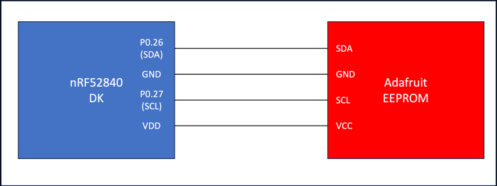
This blog post will use the Nordic nRF52840 development kit. We will connect the nRF52840 development kit to the Adafruit 24LC32 EEPROM breakout board (https://www.adafruit.com/product/5146). The following diagram shows the connections between the Adafruit breakout board and the nRF52840 development kit:
In this section, we will walk through the relevant portions of the embedded software to interface with the Adafruit EEPROM breakout board. First, we can retrieve Zephyr v3.5 using West by executing the following command:
$> west init -m <a href="https://github.com/zephyrproject-rtos/zephyr">https://github.com/zephyrproject-rtos/zephyr</a> --mr v3.5.0 zephyrproject
$> cd zephyrproject
$> west update
Second, we can clone the repository that contains our test application:
$> git clone https://github.com/mabembedded/zephyr-eeprom.git
Finally, we can connect the nRF52840 development kit to our PC using the USB connection and open a terminal interface. We can build and flash the application by executing the following commands:
$> cd zephyr-eeprom
$> cmake –preset build
$> west build && west flash
We will see the following output in the terminal interface:
*** Booting Zephyr OS build zephyr-v3.5.0 ***
Found EEPROM device "eeprom@50"
Using eeprom with size of: 4096.
Magic = 32323032
going to initialize data
Device booted 0 times.
Magic = 1e010000
Device booted 218105603 times.
Reset the MCU to see the increasing boot counter.
We can execute the following command to reset the nrF52840 development kit and rerun the application:
$> nrfjprog --reset
And we can see the following output (we expect to see the boot count increment):
*** Booting Zephyr OS build zephyr-v3.5.0 ***
Found EEPROM device "eeprom@50"
Using eeprom with size of: 4096.
Magic = 32323032
going to initialize data
Device booted 0 times.
Magic = 1e010000
Device booted 218105603 times.
Reset the MCU to see the increasing boot counter.
Obviously, something needs to be corrected. If we review the source code, the application aims to identify a region within the EEPROM that can be used to store the number of times the MCU has booted. We use a "magic value," a hard-coded 4-byte value, to delineate the start of this region. If this value is not detected, the EEPROM is "initialized" with the magic value, and the following byte, which represents the "boot count," is initialized to zero. On subsequent boots, the boot count should be incremented. Clearly, this is not happening, and my next step is to investigate the cause and hopefully find a resolution.
DEVICETREE OVERLAY
We can open the devicetree overlay to understand how support for the AT24 chip is enabled (I cover devicetree overlays in detail in my Getting Started With Zephyr: Devicetree Overlays blog post):
/ {
    aliases {
        eeprom-0 = &at24_eeprom;
    };
};
&i2c0 {
        status = "okay";
        at24_eeprom: eeprom@50 {
                compatible = "atmel,at24";
                status = "okay";
                reg = <0x50>;
                size = <4096>;
                pagesize = <32>;
                address-width = <8>;
                timeout = <5>;
        };
};
I create an "alias" at the root of the devicetree for an "eeprom-0" node, which is referenced in the source code. Then, I ensure that the primary i2c bus is enabled by referencing it and ensuring the "status" attribute is set to "okay." I then create a node inside the i2c bus that represents the EEPROM. The "compatible" attribute enables the AT24 driver in Zephyr's EEPROM subsystem. This is done by linking the Kconfig under drivers/eeprom to the devicetree binding, as shown below:
config EEPROM_AT24
        bool "Atmel AT24 (and compatible) I2C EEPROM support"
        default y
        depends on DT_HAS_ATMEL_AT24_ENABLED
        select I2C
        select EEPROM_AT2X
        help
          Enable support for Atmel AT24 (and compatible) I2C EEPROMs.
The "DT_HAS_ATMEL_AT24_ENABLED" macro uses the compatible string to identify whether the AT24 device is present and enables the driver.
The "reg" attribute sets the I2C address of the EEPROM. Subsequent attributes set the relevant values of the chip.
KCONFIG
The Kconfig for this application is minimal, as shown below:
CONFIG_PRINTK=y
CONFIG_EEPROM=y
CONFIG_MAIN_STACK_SIZE=2048
CONFIG_HEAP_MEM_POOL_SIZE=512
CONFIG_GPIO=y
The only relevant configuration option is "CONFIG_EEPROM."
APPLICATION SOURCE
We use the alias specified in the devicetree in the "get_eeprom_device" function, which returns a pointer to the device representing the EEPROM chip:
static const struct device *get_eeprom_device(void)
{
        const struct device *const dev = DEVICE_DT_GET(DT_ALIAS(eeprom_0));
.
.
}
Here, we can see that the function uses the devicetree binding macros to retrieve the alias specified in the devicetree. It then ensures that the device is ready and prints the device's name if it is. If not, it returns an error.
In main, we use the EEPROM API calls in Zephyr to perform the necessary operations. First, "eeprom_get_size" is used to retrieve and report the capacity of the EEPROM chip:
eeprom_size = eeprom_get_size(eeprom);
printk("Using eeprom with size of: %zu.\n", eeprom_size);
Then, we use the "eeprom_read" and "eeprom_write" functions to interact with the EEPROM chip:
rc = eeprom_read(eeprom, EEPROM_SAMPLE_OFFSET, &values, sizeof(values));
.
.
rc = eeprom_write(eeprom, EEPROM_SAMPLE_OFFSET, &values, sizeof(values));
Using the generic API calls of the Zephyr EEPROM subsystem frees us from knowing the underlying implementation details of the specific driver or hardware. We simply need to enable the appropriate device in the devicetree and the Zephyr build and driver infrastructure take care of the rest.
SUMMARY
In this blog post, I showed how to implement a Zephyr application to interact with an EEPROM chip. I showed how to use the devicetree to make Zephyr aware of this chip's presence and enable the appropriate driver. I then showed how using the high-level Zephyr API calls frees us from the underlying implementation details of the specific driver. I hope to resolve the issues shown in the current implementation and let all of you know!


- Comments
- Write a Comment Select to add a comment
A way more useful set of code here would be some basic I2C driver to give me access to the bus, create the various start, restart, stretching and stop conditions and deal with the various error conditions on it and let me write what I need to do with the E2 (it's fall off a log simple). This sort of demo is far more useful as it would show how to deal with a deeper layer and get rid of the superfluous upper layers. It allows more generic code and far more complex things like multi-threaded interactions with multiple peripherals on the same bus and oddball things like odd bit sequences of strange peripherals or things where I need to do restarts and that kind of interaction.
@randylee - this is how to write data to the EEPROM which just happens to be on the I2C bus. If you want to learn how to use the I2C driver, then take a look at the documentation for that: https://docs.zephyrproject.org/latest/hardware/per...
The whole idea of the driver layers in Zephyr is that you do not have to worry about the I2C protocol details. This is normally fine for most use cases. If you have buggy hardware or need to do something special, then you can always write your own I2C driver or bypass the existing driver in your code and handle all of the details in your application code, but at that point I would question if going bare metal would be a better fit for that approach.

Thanks, @randylee and @eric2022 for your comments!
@randylee, coming from a Linux background, Zephyr aligns more closely with the Linux paradigm of software development.
As @eric2022 mentioned, if someone wants to use an EEPROM in their application, they must assume that the EEPROM driver works correctly. The advantage is that they can focus on the application. The disadvantage is that there is the possibility that the driver is buggy and they have to devote time to it (the advantage with Zephyr is that there is a large and organized community, and help is usually easy to get).
Personally, I like this paradigm for several reasons. First, if I'm developing a driver, there's a fixed API that I need to target, which reduces development time. Second, suppose I'm writing an application targeting a particular subsystem. In that case, I can use the API function calls without worrying about the underlying driver and hardware details (to some degree). Then, if/when the hardware changes, I would just need to change the devicetree, but NOT the source code.
I'll take a gander at your link and see if I can decipher what is going on there...
When I write, I write for lowest denominator as then I have the most flexibility so I would never, ever, use the E2 driver. Ever. That particular thing is so easy it makes zero sense to have the problems of other peoples code to worry about.
And using that sort of a driver would also preclude the interaction of all kinds of other things on that bus, particularly when multiple threads are involved in using the bus for their own chips.
As to worrying about I2C protocols: as an embedded engineer, I sure the hell do worry about the protocols because I've seen way too often where it screws up. At that point, if you don't have a logic analyzer on that bus and watching what's going on and relating that back into the code stack, you are screwed.
And, BTW, I often watch the bus traffic so that I know what's going on in and between the code. Better than blinky lights (which I adore).
@randylee - the drivers have logging and there are tracing frameworks that can help track down bugs, keep a pulse on the system, and also help you do post mortum analysis. The real use case for Zephyr RTOS and other RTOSs in general are to allow you to focus on the application code and more easily switch hardware. The same abstraction is also used for unit testing so you can run the system on your local PC which is extremely useful at tracking down bugs and keeping them squashed. I still definitely have a logic analyser on the boards at my desk during development, but that is normally only during the first week or two of hardware bringup and after that I rely upon error checking and logs to track down most issues which also helps with field failures. Just a different approach to development that works well in fast-paced environments and when faced with chip shortages. If you have time to do custom-coded software and never have to worry about chip shortages, then you are really lucky.
To post reply to a comment, click on the 'reply' button attached to each comment. To post a new comment (not a reply to a comment) check out the 'Write a Comment' tab at the top of the comments.
Please login (on the right) if you already have an account on this platform.
Otherwise, please use this form to register (free) an join one of the largest online community for Electrical/Embedded/DSP/FPGA/ML engineers:

