


Intro to Microcontrollers
Introduction
Probably one of the greatest inventions in the world of electronics is the microcontroller. These are integrated circuit chips which can be programmed to interface with a wide variety of sensors, actuators, and other electrical components. They're general low-power and are fairly wimpy compared to an actual computer, or even many people's mobile devices.
I've had previous experience with microcontrollers using the Arduino Platform. This is a wonderful little board with an AVR microcontroller, USB port, and various IO pin functions. However, Arduinos aren't really that cheap. It's possible to get one for around $20 US, though they can get up to $60 or so if you get one of the bigger Arduino Megas. To contrast this, there are many microcontrollers available for under $5. These won't have all of the capabilities as the microcontroller used by Arduinos, but many times this isn't necessary. For my testing I'm going to use an ATtiny24A AVR microcontroller. It's an extremely low-power 14-pin microcontroller which can run up to 20 MHz. There's 2K of flash program memory, 128 bytes of EEPROM, and 128 bytes of SRAM.
Programming
Before I can do any playing/testing with this microcontroller I need to be able to program the device. Now I could go and purchase an AVR programmer (there are several on the market), but I happen to have an Arduino Mega board, which has in-system programming (ISP) capabilities.
There's a nice guide on the Arduino Playground which shows how to use the Arduino with AVRDude to upload a hex file. Personally I prefer this method because on ATtiny chips their's usually very little memory space so every byte counts. I don't need/want the Arduino convenience libraries, it's just adding wasted space to my device. This may not be the path that everyone wants to take. Some people like using the Arduino libary because it simplifies things. For those people, MIT has put out a nice little tutorial about how to add a device to the Arduino IDE. They use the ATtiny45/ATtiny85 as examples, but it shouldn't be too hard to adapt this to whatever chip you have.
So let's get started!
Before I can use the Arduino as an ISP, it needs to have the appropriate firmware uploaded. The Arduino software comes with an ArduinoISP example which does just this. Upload the firmware using the Arduino IDE to my board and I'm good to go.
I also need a way to upload my program. As stated above I don't want to use the Arduino libraries, I just want to use the ArduinoISP as a raw uploader of my pre-compiled hex. This is where the AVRDude software comes in. This is a simple command-line utility for programming chips using the in-system programmer. For Windows the easiest way to get the AVRDude program is to use WinAVR. This contains several tools which allow you to compile, debug, and upload programs to your AVR device.
The ArduinoISP functions by using the Serial Peripheral Interface Bus (SPI) functionality found in the AVR microcontroller used by the Arduino board. The main thing I need to do is connect the SPI pinout from the Arduino the the SPI pinout of my ATtiny24A.
Checking the Arduino SPI documentation, it looks like my Mega board has the following pinout:
- MOSI: Pin D51
- MISO: Pin D50
- SCK: Pin D52
- SS (slave mode): Pin D53
There is also an ICSP header which has a convenient 6-pin layout for the SPI interface, but I'm not going to use this as I don't have the female header to use this. The Arduino is the master device and my ATtiny24A is the slave device. The ArduinoISP firmware uses the SS pin as an output to control the target device reset pin.
The corresponding pinouts on the ATtiny24A (I'm using the PDIP package):
- VCC: Pin 1
- GND: Pin 14
- RESET: Pin 4
- MOSI: Pin 7
- MISO: Pin 8
- SCK: Pin 9
So I need to make the following connections (Arduino : ATtiny24A):
- 5V : Pin 1
- GND : GND
- Pin D50 : Pin 8
- Pin D51 : Pin 7
- Pin D52 : Pin 9
- Pin D53 : Pin 4
In addition to this, to prevent my Arduino from auto-restarting on COM initialization, I added a 10 uF capacitor between the Arduino's RESET pin and ground.
Now to test if everything's working correctly. First, let's check to make sure that the ArduinoISP and ATtiny24A chip are supported by my current version of AVRDude.
avrdude -p ?
This lists all supported target devices. In my case, I didn't find the ATtiny24A exactly, however I did find the ATtiny24 chip which is very similar. Reading through the datasheet for that chip and it looks like it uses the same ISP protocol as the ATtiny24A so I should be good to use the same target. The target device ID is t24.
avrdude -c ?
This lists all supported programmers. I found the ArduinoISP listed as arduino.
Now to do a test. ArduinoISP runs by default at a baudrate of 19200. I've increased this speed up to 115200 by editing the code, I'll see if this speed is stable, though I think it will be.
I happen to know that my Arduino Mega is on port COM6. You can check the Arduino IDE for what port the device is on (it's the same one as the one you uploaded the ArduinoISP firmware). Here's the base command I'll need for using the avrdude utility.
avrdude -p t24 -c arduino -P COM6 -b 115200
Running this code and I got the following reply:
avrdude: please define PAGEL and BS2 signals in the configuration file for part ATtiny24
avrdude: AVR device initialized and ready to accept instructions

Reading | ################################################## | 100% 0.03s

avrdude: Device signature = 0x1e910b

avrdude: safemode: Fuses OK

avrdude done.  Thank you.
I'm not entirely sure why it asks me to define the PAGEL and BS2 signals, these are STK500 parallel programming parameters. It does work, though.
To read/write to the device there's the -U option. This can be chained multiple times in a call to avrdude. It can be used to read/write fuse bits, write a program to flash, write contents to the EEPROM, etc. I would recommend reading the avrdude documentation for this command as it's pretty good at describing what different parameters you can use.
4-digit 7-segment LED
The first project I want to try is driving a 4-digit 7-segment LED display. The display I'm using is the LTC-4627JR, but any common-anode 4-digit 7-segment display will do.
First, let's take a look at the internal schematic for this display.
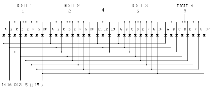
The way this type of display works is that it rapidly switches between each digit, faster than the human eye can detect. This gives the appearance that the display is static when in reality it is dynamically updating itself. These multiplexed displays are used to reduce the number of pins required to drive the display. If this display wasn't multiplexed, there would be a total of 35 pinouts. As it currently is, there are 8 pinouts for each segment and 1 pinout for each digit, giving a total of 13 pins. There is a fifth partial digit pinout for a few dots around the display, but I'm not using that.
Here's a schematic of the entire circuit.
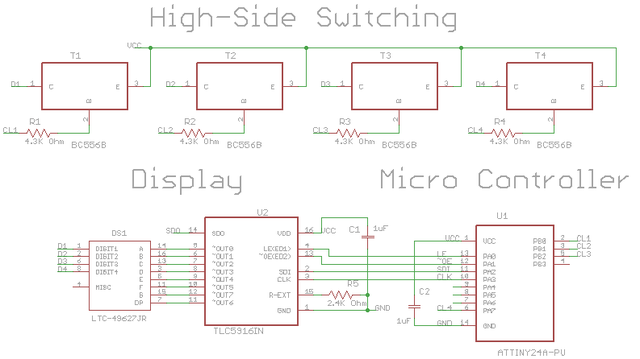
LED's draw a significant amount of current, enough to potentially damage the microcontroller. The common digit source pins have at max 8 segments/LEDs that could be on at any one time. The maximum current specified through each segment is 25 mA, and I'm planning on driving these at 10mA. That gives a maximum current draw of 80 mA. The datasheet for the ATtiny24A recommends against sourcing/sinking more than 60 mA total from all the IO pins, so I need external circuitry to drive the LEDs safely.
Luckily, there are special LED driver IC's which provide a constant current source for the LED's. The chip I'm using is the TLC5961 because it has the ability to drive a maximum of 8 different LEDs with any combination of them on or off.
The TLC5916 is a sink type driver, meaning that the current flows from the positive supply, through the LED, through the driver, then to ground. This will work for controlling individual segments, but I still need to be able to multiplex through the different digits.
Rather than looking for a source type driver I decided I would use PNP transistors. P-channel MOSFETs would work just as well, possibly better, but I chose the PNP transistors because they're cheaper than the MOSFETs. The specific part I'm using is the BC556BTA.
The resistor R5 was chosen at \(2.4 k\Omega\) by looking at figure 15 the TLC5916 datasheet. Basically it sets the target output current just under 10 mA (calculated to be 7.81mA) with the default chip settings. PNP transistors have the potential to sink significant current through the base. Resistors R1-R4 do this by limiting the amount of current from the emitter to the base. I need about 62.5mA max output from the collector (7.81mA for each segment), and ideally I would like the PNP transistor to be in saturation mode since current is being regulated by the LED sink driver anyways.
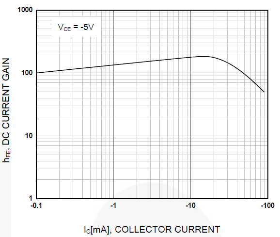
A BJT transistor is in saturation mode if both junctions are forward biased. In the case of a PNP transistor, this means the base voltage is less than the collector and emitter voltages. The idea is that the current from the emitter to the collector is controlled by external circuitry, not the transistor. Using the h-parameter model, this translates to equation \eqref{base_current}.
\[ h_{fe} \cdot i_B < i_C \label{base_current} \]
Figure 3 shows the \(h_{fe}\) as a function of collector current. At ~62mA, \(h_{fe} \approx 65\). Therefore the absolute minimum base current I should have is \(962 \mu A\).
Looking at the emitter/base voltage characteristics of the BC556BTA (figure 4), there is ~0.8 V difference between the emitter and the base. Assuming that my microcontroller can pull the IO pin to ground (it can get close, especially for such low currents), I can solve for the minimum resistance required in equation \eqref{pnp_resistor}.

\[ R_{max} = \frac{V_{s} - V_{eb}}{I_b} = \frac{5V - 0.8V}{962 \mu A} = 4.37 k\Omega \label{pnp_resistor} \]
I happen to have a \(4.3 k\Omega\) resistor which is pretty close to this maximum value while still being under. Note that I am relying on the assumption that figure 3 shows the minimum values for \(h_{fe}\) vs. \(i_c\). This appears to be the case because the datasheet specifies a minimum \(h_{fe}=110\) for \(i_c = 2 mA\), which matches the graph under the same conditions. Even so, it's a good idea to design with an appropriate margin of safety. A smaller resistor like a \(3.3 k\Omega\) would be better, but oh well. I measured the voltages across the transistor pins and mine were all saturated perfectly fine using the \(4.3 k\Omega\) resistors I had.
The capacitors in the schematic are decoupling capacitors. If you follow the questions asked over at Electronics Stack Exchange for any period of time, there's usually a question every week or so asking about these. These are basically "local power sources" for the nearby circuits. The idea is that the main power rail charges up the decoupling capacitors and any power drawn by the device comes from the capacitors, not the rail itself. This provides a smoother supply voltage to the individual chips and helps to reduce noise in the system. It's not uncommon to have multiple capacitors of different values (a common setup is a 100nF/1uF/10uF combo), though I won't go into the details too much here. It has to deal with the impedance response of real capacitors vs. signal frequency. Basically you want a low impedance path from all high frequency signals to ground so they don't reach your device. It's also important to place them as close to each individual chip as possible, with the smallest ones being closer.
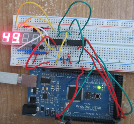
My circuit isn't terribly fast, I tested the signals between the LED driver and microcontroller, and the signals were about 36 kHz or so. The core clock of the microcontroller is faster at 8 MHz. I dug into my parts bin and found some ceramic 1uF capacitors, stuck them in, and called it good because everything worked. Note that without these caps in there the circuit simply refused to work so it is important to have them in there.
Now that I have my circuit, I need to write the code. To keep things simple I'm using a basic bit-banging technique to shift data into the LED driver.
/*
 * display_driver.h
 *
 *  Author: helloworld922
 */


#ifndef DISPLAY_DRIVER_H_
#define DISPLAY_DRIVER_H_

#include <avr/io.h>
#include <avr/pgmspace.h>

#define SEG_A 1 << 7
#define SEG_B 1 << 6
#define SEG_C 1 << 5
#define SEG_D 1 << 4
#define SEG_E 1 << 3
#define SEG_F 1 << 2
#define SEG_G 1
#define SEG_DP 1 << 1

// display data in
#define SDI_PORT PORTA
#define SDI_PIN 2

// display clock
#define CLK_PORT PORTA
#define CLK_PIN 3

// display strobe data
#define LE_PORT PORTA
#define LE_PIN 0

// display output enable
#define OE_PORT PORTA
#define OE_PIN 1

#define DIG1_PORT PORTB
#define DIG1_PIN 0

#define DIG2_PORT PORTB
#define DIG2_PIN 1

#define DIG3_PORT PORTB
#define DIG3_PIN 2

#define DIG4_PORT PORTA
#define DIG4_PIN 7

void write_display(const uint8_t data[4], const bool dp[4]);

void write_digit(volatile uint8_t& digit_port, const uint8_t digit_pin, volatile uint8_t& last_digit_port, const uint8_t last_digit_pin, const uint8_t value, const bool dp);

inline void init_display(void)
{
 // set SDI, CLK, LE, OE, and all digits to output
 DDRA |= (1 << CLK_PIN) | (1 << LE_PIN) | (1 << OE_PIN) | (1 << DIG4_PIN) | (1 << SDI_PIN);
 DDRB &= ~(1 << PORTB3);
 DDRB |= (1 << DIG1_PIN) | (1 << DIG2_PIN) | (1 << DIG3_PIN);
 // disable all segments
 write_digit(DIG1_PORT, DIG1_PIN, DIG1_PORT, DIG1_PIN, 10, false);
 // disable all digits
 DIG1_PORT |= 1 << DIG1_PIN;
 DIG2_PORT |= 1 << DIG2_PIN;
 DIG3_PORT |= 1 << DIG3_PIN;
 DIG4_PORT |= 1 << DIG4_PIN;
 // enable output
 OE_PORT &= ~(1 << OE_PIN);
}

#endif /* DISPLAY_DRIVER_H_ */
/*
 * display_driver.cpp
 *
 * Display driver for LTC-4627JR
 *
 *  Author: helloworld922
 */

#include "display_driver.h"

/**
 * Value order:
 * '0', '1', '2', '3', '4', '5', '6', '7', '8', '9', ' '
 */
const static uint8_t PROGMEM display_lut[] = {  SEG_A | SEG_B | SEG_C | SEG_D | SEG_E | SEG_F,
            SEG_B | SEG_C,
            SEG_A | SEG_B | SEG_D | SEG_E | SEG_G,
            SEG_A | SEG_B | SEG_C | SEG_D | SEG_G,
            SEG_B | SEG_C | SEG_F | SEG_G,
            SEG_A | SEG_C | SEG_D | SEG_F | SEG_G,
            SEG_A | SEG_C | SEG_D | SEG_E | SEG_F | SEG_G,
            SEG_A | SEG_B | SEG_C,
            SEG_A | SEG_B | SEG_C | SEG_D | SEG_E | SEG_F | SEG_G,
            SEG_A | SEG_B | SEG_C | SEG_D | SEG_F | SEG_G,
            0};

void write_display(const uint8_t data[4], const bool dp[4])
{
 write_digit(DIG1_PORT, DIG1_PIN, DIG4_PORT, DIG4_PIN, data[0], dp[0]);
 write_digit(DIG2_PORT, DIG2_PIN, DIG1_PORT, DIG1_PIN, data[1], dp[1]);
 write_digit(DIG3_PORT, DIG3_PIN, DIG2_PORT, DIG2_PIN, data[2], dp[2]);
 write_digit(DIG4_PORT, DIG4_PIN, DIG3_PORT, DIG3_PIN, data[3], dp[3]);
}

void write_digit(volatile uint8_t& digit_port, const uint8_t digit_pin, volatile uint8_t& last_digit_port, const uint8_t last_digit_pin, const uint8_t value, const bool dp)
{
 uint8_t code = pgm_read_byte(display_lut + value) | (dp ? SEG_DP : 0);
 // shift in the first 7 bits
 for(uint8_t i = 8; i != 0; --i)
 {
  // write the LSB of code to SDI
  SDI_PORT = (SDI_PORT & ~(1 << SDI_PIN)) | ((code & 0x1) << SDI_PIN);
  // clock high
  CLK_PORT |= (1 << CLK_PIN);
  // clock low
  CLK_PORT &= ~(1 << CLK_PIN);
  // shift value
  code >>= 1;
 }
 // disable the last digit
 last_digit_port |= 1 << last_digit_pin;
 // enable the current digit
 digit_port &= ~(1 << digit_pin);

 // strobe data high
 LE_PORT |= (1 << LE_PIN);
 // strobe data low
 LE_PORT &= ~(1 << LE_PIN);
}
/*
 * AtTiny_7_Segment.cpp
 *
 *  Author: helloworld922
 */

 #include <avr/io.h>
 #include "display_driver.h"

int main(void)
{
 // initialization
 init_display();
 uint8_t data[4];
 bool dp[4];
 data[0] = 1;
 data[1] = 2;
 data[2] = 10;
 data[3] = 10;
 dp[0] = false;
 dp[1] = true;
 dp[2] = false;
 dp[3] = false;
    while(true)
    {
  for(uint8_t i = 0; i < 10; ++i)
  {
   for(uint8_t j = 0; j < 10; ++j)
   {
    data[0] = i;
    data[1] = j;
    for(unsigned int k = 0x100; k != 0; --k)
    {
     write_display(data, dp);
    }
   }
  }
    }
}
This code just cycles through the first two digits in a counter. The main test code isn't that great, but it works. To upload the compiled code (I'm using the Intel Hex file format):
avrdude -p t24 -c arduino -P COM6 -b 115200 -U flash:w:"AtTiny 7 Segment.hex":i
Last Thoughts
This was a pretty fun project. In the future I'll definitely have to consider getting/making a programming cable assembly as the loose wires to the Arduino was a big pain. When I first looked at the specs for the ATtiny24A I chuckled at how little memory I had to work with, but after doing some programming I realized that there's a suprisingly large number of stuff you can do with this little guy. The compiler notified me that the program could run using 478 bytes of flash and 0 bytes of SRAM/EEPROM. Not bad at all :)


- Comments
- Write a Comment Select to add a comment
To post reply to a comment, click on the 'reply' button attached to each comment. To post a new comment (not a reply to a comment) check out the 'Write a Comment' tab at the top of the comments.
Please login (on the right) if you already have an account on this platform.
Otherwise, please use this form to register (free) an join one of the largest online community for Electrical/Embedded/DSP/FPGA/ML engineers:


