


Linear Feedback Shift Registers for the Uninitiated, Part VII: LFSR Implementations, Idiomatic C, and Compiler Explorer
The last four articles were on algorithms used to compute with finite fields and shift registers:
- multiplicative inverse
- discrete logarithm
- determining characteristic polynomial from the LFSR output
Today we’re going to come back down to earth and show how to implement LFSR updates on a microcontroller. We’ll also talk a little bit about something called “idiomatic C” and a neat online tool for experimenting with the C compiler.
Galois LFSR Implementation Revisited: Trust but Verify
I already showed one implementation in Part I of this series. There are a few questions:
- Does it do what we want?
- Does it do it efficiently?
Normally I would handle this in the order shown above, but let’s handle the “efficiently” question, at least in part, by looking at the compiler output for one processor. I talked about looking at the output of the compiler in one article a few years ago, and since I use the dsPIC33EP256MC506 frequently, we’ll look at the XC16 compiler output using pyxc16, which I talked about in that article.
Here’s the code from part I (with lfsr_step renamed to lfsr_step1, since we’re going to rewrite it a couple of times), along with the dsPIC33E assembly produced by the XC16 with -O1 optimization:
import pyxc16

pyxc16.compile('''
#include <stdint.h>
#include <stdbool.h>

typedef struct {
    uint32_t state;
    uint32_t taps;
    uint32_t ymask;
} LFSR_T;

LFSR_T lfsr;

void lfsr_init(LFSR_T *plfsr)
{
    plfsr->state = 1;
    plfsr->taps  = 0x0005; // a0 = 1, a2 = 1
    plfsr->ymask = 0x0010; // bit 4 is the highest significant state bit
}

/* Galois implementation of LFSR */
bool lfsr_step(LFSR_T *plfsr)
{
    bool out = (plfsr->state & plfsr->ymask) != 0;
    plfsr->state <<= 1;    // shift left
    if (out)
    {
        plfsr->state ^= plfsr->taps;
        /* flip bits connected to the taps if the output is 1.
           Note that the state bits beyond bit 4 are ignored */
    }
    return out;
}
''', '-c', '-O1', '-fverbose-asm')
_lfsr_init: mov #1,w2 ;, tmp43 mov #0,w3 ;, tmp43 mov.d w2,[w0] ; tmp43, plfsr_1(D)->state mov #5,w2 ;, tmp44 mov #0,w3 ;, tmp44 mov w2,[w0+4] ; tmp44, plfsr_1(D)->taps mov w3,[w0+6] ; tmp44, plfsr_1(D)->taps mov #16,w2 ;, tmp45 mov #0,w3 ;, tmp45 mov w2,[w0+8] ; tmp45, plfsr_1(D)->ymask mov w3,[w0+10] ; tmp45, plfsr_1(D)->ymask return _lfsr_step: mov.d [w0],w4 ; plfsr_1(D)->state, D.2050 mov [w0+8],w2 ; plfsr_1(D)->ymask, plfsr_1(D)->ymask mov [w0+10],w3 ; plfsr_1(D)->ymask, plfsr_1(D)->ymask and w2,w4,w1 ; plfsr_1(D)->ymask, D.2050, tmp53 and w3,w5,w6 ; plfsr_1(D)->ymask, D.2050, tmp54 clr w7 ; tmp59 sl w6,#0,w3 ; tmp59,, tmp51 mov #0,w2 ; tmp51 mul.uu w1,#1,w6 ; tmp53, tmp59 ior w2,w6,w2 ; tmp51, tmp59, tmp51 ior w3,w7,w3 ; tmp51, tmp59, tmp51 ior w3,w2,w2 ;, tmp51, tmp60 mov w2,w1 ; tmp60, tmp61 btsc w1,#15 ; tmp61 neg w1,w1 ; tmp61, tmp61 neg w1,w1 ; tmp61, tmp62 lsr w1,#15,w2 ; tmp62,, out add w4,w4,w4 ; D.2050, D.2053 addc w5,w5,w5 ; D.2050, D.2053 mov.d w4,[w0] ; D.2053, plfsr_1(D)->state cp0.b w2 ; out bra z,.L3 ; mov [w0+4],w6 ; plfsr_1(D)->taps, plfsr_1(D)->taps mov [w0+6],w7 ; plfsr_1(D)->taps, plfsr_1(D)->taps xor w4,w6,[w0++] ; D.2053, plfsr_1(D)->taps, plfsr_1(D)->state xor w5,w7,[w0--] ; D.2053, plfsr_1(D)->taps, plfsr_1(D)->state .L3: mov.b w2,w0 ; out, return _lfsr: .space 12
The efficiency of the lfsr_init function doesn’t matter much to us, since it will just be called once. What we care about is the code for lfsr_step; there’s a lot going on there! Excluding the return, we’ve got 27 instructions that take 29 cycles worst-case; mov.d is a double-word move that takes two cycles, and all the other instructions take one cycle each, except for branches and jumps if taken. (A conditional branch takes one instruction and acts as a NOP if not taken, but if there is a branch, it takes 4 cycles. CALL and RETURN together take 10 cycles. There are a few other quirks, like interaction with chip special function registers taking 2 cycles rather than one, but if you’re just interacting with the 16 W registers and RAM, all the basic instructions take one cycle each.)
Such a large assembly implementation wasn’t what I expected here, and perhaps we should try rewriting it.
Let’s look at implementing an LFSR at a very low level: assembly language!
LFSR Updates in Assembly
I should say that I hate writing assembly… except in snippets for cases like this, and I don’t actually write the assembly completely, I let the compiler do it for me. (Never mind the nuances for now, I’ll come back to this later.)
Since this is a shift register, we have to understand how to perform a shift. Most processors have some kind of shift-left and shift-right instructions, and what they do is, um, shift bits left or right. Here’s a shift left operation:
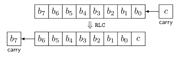
This diagram shows an 8-bit byte before and after a shift operation. I’ve labeled this RLC which stands for Rotate Left through Carry, which is an instruction on the dsPIC architecture. To be more pedantic: the dsPIC is a 16-bit architecture, but most of its instructions can operate on 16-bit words or 8-bit bytes; an 8-bit rotate is RLC.B, whereas the default RLC operates on a 16-bit register. The only reason I’m showing 8 bits here is that it’s a little easier on the eyes than a 16-bit register. RLC.B operates on a byte stored somewhere (either a working register or a memory location), and on the carry bit in the chip’s status register. The carry value shifts in to the least significant bit, the other 7 bits shift up, and the most-significant bit of the original byte shifts out into the carry bit.
Another way of looking at this is to blur the “before” and “after” situations and instead emphasize the “rotate” part of Rotate Left through Carry:
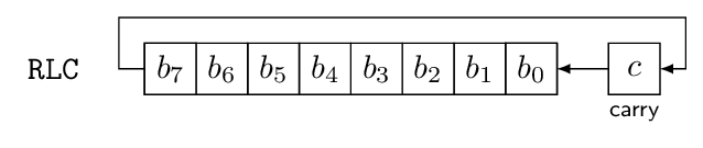
There’s also a SL instruction which operates exactly the same as RLC except that it shifts a 0 in on the right, instead of the carry bit. If you want to perform an 8-bit or a 16-bit shift, you can do it in one instruction. If you have some other number of bits to shift that is smaller than a 16-bit word, you can do it in one instruction and just ignore the upper bits — for example, if you have a 6-bit shift register containing 110101 stored in an 8-bit byte as 00110101 and you shift it left using SL.B, you’ll get 01101010, so we can just ignore the top two bits and be done with it. Or, if you’re a neatness freak, you can AND the 8-bit storage location with a 6-bit mask 00111111 and clear out the top two bits.
What if we have more than 16 bits? The SL and RLC instructions are intended to cascade easily by rotating through the carry bit, just like the RLC instruction signifies. Here’s a 48-bit shift using 6 instructions, one after the other:
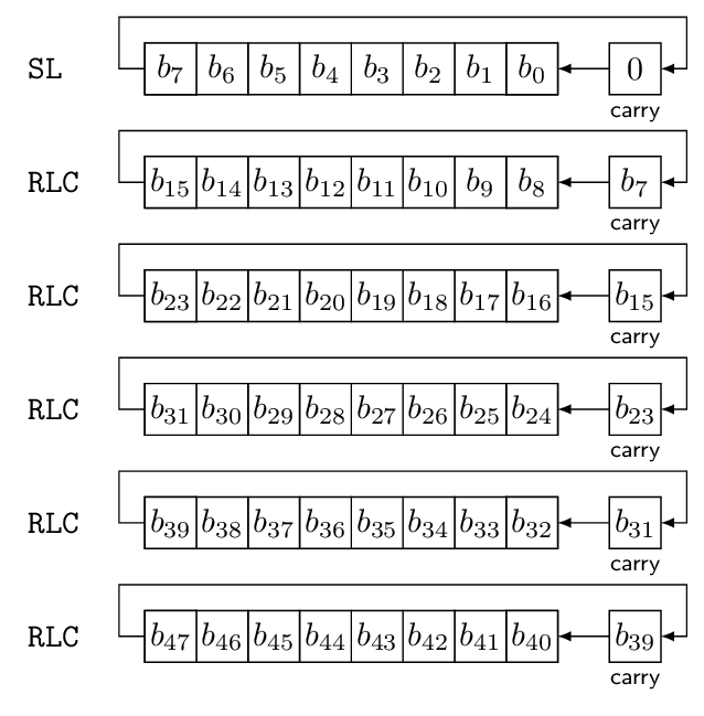
At each step, the most significant bit of the byte shifts out into the carry, from which it can be shifted in to the next byte using RLC.B. At the end, the most significant bit (\( b_{47} \) in this case) ends up in the carry bit for further use, should we want to.
We could do the same thing with RLC instructions operating on 16-bit words, completing a 48-bit shift in 3 instructions:
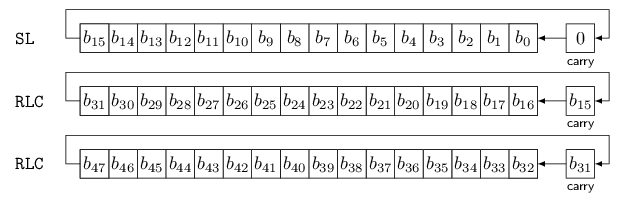
(See what I mean? The 16-bit diagrams are too cluttered to look as good as a nice clean 8-bit diagram.)
Okay, so that should take 2 instructions for a 32-bit shift and 3 instructions for a 48-bit shift. How did we get from 2 instructions to 27 instructions?
Well, a left-shift is only one part of the LFSR update process; the rest of it involves looking at the topmost bit that we shifted out, and using it to XOR in a mask representing the polynomial. At a bare minimum, that involves at least 3 more instructions (2 XORs for a 32-bit LFSR, plus some kind of conditional skip or jump), and probably a few more instructions for moving things around. You’ll find that when you work with assembly, the MOV instructions tend to add up, just like those odd-sounding extra fees and taxes on a bill — concession recovery fee, domestic security fee, regulatory surcharge — you can grumble all you want, but you can’t avoid them. In the listing above, 9 out of 27 instructions were MOV, taking 11 cycles out of 29 cycles total.
Okay, let’s try to get smarter here. Part of the cost of the lfsr_step1 implementation is to figure out whether the high bit of the initial state is 1, and we did it using a bitmask operation that compared the result with zero:
bool out = (plfsr->state & plfsr->ymask) != 0;
To do this, the compiler has to perform a 32-bit AND operation and a 32-bit comparison with zero, which take a bunch of cycles. Now, we know that the mask is only 1 bit, but the compiler doesn’t. We only really care about one particular bit, so maybe we can use a shift-right approach to examine that bit:
bool out = (plfsr->state >> plfsr->nminus1) & 1;
Here’s another version of lfsr_step using this approach:
pyxc16.compile('''
#include <stdint.h>
#include <stdbool.h>

typedef struct {
    uint32_t state;
    uint32_t taps;
    unsigned int nminus1;
} LFSR_T;


/* Galois implementation of LFSR */
bool lfsr_step2(LFSR_T *plfsr)
{
    bool out = (plfsr->state >> plfsr->nminus1) & 1;
    plfsr->state <<= 1;    // shift left
    if (out)
    {
        plfsr->state ^= plfsr->taps;
        /* flip bits connected to the taps if the output is 1.
           Note that the state bits beyond bit 4 are ignored */
    }
    return out;
}
''', '-c', '-O1', '-fverbose-asm')
_lfsr_step2: mov.d [w0],w2 ; plfsr_1(D)->state, D.2044 mov [w0+8],w1 ; plfsr_1(D)->nminus1, plfsr_1(D)->nminus1 mov.d w2,w4 ; D.2044, tmp53 .LB9: dec w1,w1 ; plfsr_1(D)->nminus1 bra n,.LE9 lsr w5,w5 ; tmp53, tmp53 rrc w4,w4 ; tmp53, tmp53 bra .LB9 .LE9: and.b w4,#1,w1 ; tmp53,, out add w2,w2,w2 ; D.2044, D.2049 addc w3,w3,w3 ; D.2044, D.2049 mov.d w2,[w0] ; D.2049, plfsr_1(D)->state cp0.b w1 ; out bra z,.L2 ; mov [w0+4],w4 ; plfsr_1(D)->taps, plfsr_1(D)->taps mov [w0+6],w5 ; plfsr_1(D)->taps, plfsr_1(D)->taps xor w2,w4,[w0++] ; D.2049, plfsr_1(D)->taps, plfsr_1(D)->state xor w3,w5,[w0--] ; D.2049, plfsr_1(D)->taps, plfsr_1(D)->state .L2: mov.b w1,w0 ; out, return
Okay… well, the code is shorter in terms of program size, but now we have a loop (from .LB9 to .LE9) executed plfsr->nminus1 times. That’s no good. Hmm.
All right, we’ll try something else. A lot of times we don’t actually care about the return value, so why not ignore it if we don’t need it? In the following code lfsr_step3_noreturn saves 2 cycles by not having to produce an output.
pyxc16.compile('''
#include <stdint.h>
#include <stdbool.h>

typedef struct {
    uint32_t state;
    uint32_t taps;
    unsigned int nminus1;
} LFSR_T;


/* Galois implementation of LFSR */
inline static bool lfsr_step3(LFSR_T *plfsr)
{
    bool out = (plfsr->state >> plfsr->nminus1) & 1;
    plfsr->state <<= 1;    // shift left
    if (out)
    {
        plfsr->state ^= plfsr->taps;
        /* flip bits connected to the taps if the output is 1.
           Note that the state bits beyond bit 4 are ignored */
    }
    return out;
}

void lfsr_step3_noreturn(LFSR_T *plfsr)
{
    lfsr_step3(plfsr);
}
''', '-c', '-O1', '-fverbose-asm', '-finline')
_lfsr_step3_noreturn: mov.d [w0],w2 ; plfsr_1(D)->state, D.2071 mov [w0+8],w1 ; plfsr_1(D)->nminus1, plfsr_1(D)->nminus1 mov.d w2,w4 ; D.2071, tmp51 .LB9: dec w1,w1 ; plfsr_1(D)->nminus1 bra n,.LE9 lsr w5,w5 ; tmp51, tmp51 rrc w4,w4 ; tmp51, tmp51 bra .LB9 .LE9: add w2,w2,w2 ; D.2071, D.2066 addc w3,w3,w3 ; D.2071, D.2066 mov.d w2,[w0] ; D.2066, plfsr_1(D)->state btst w4,#0 ; tmp51, bra z,.L1 ; mov [w0+4],w4 ; plfsr_1(D)->taps, plfsr_1(D)->taps mov [w0+6],w5 ; plfsr_1(D)->taps, plfsr_1(D)->taps xor w2,w4,[w0++] ; D.2066, plfsr_1(D)->taps, plfsr_1(D)->state xor w3,w5,[w0--] ; D.2066, plfsr_1(D)->taps, plfsr_1(D)->state .L1: return
But we still have that damned loop. What if we know the size of the LFSR at compile time, for example suppose we know we have a 31-bit LFSR:
pyxc16.compile('''
#include <stdint.h>
#include <stdbool.h>

typedef struct {
    uint32_t state;
    uint32_t taps;
} LFSR_T;


/* Galois implementation of LFSR */
inline static bool lfsr_step3(LFSR_T *plfsr, unsigned int nminus1)
{
    bool out = (plfsr->state >> nminus1) & 1;
    plfsr->state <<= 1;    // shift left
    if (out)
    {
        plfsr->state ^= plfsr->taps;
        /* flip bits connected to the taps if the output is 1.
           Note that the state bits beyond bit 4 are ignored */
    }
    return out;
}

void lfsr_step3_noreturn(LFSR_T *plfsr, unsigned int nminus1)
{
    lfsr_step3(plfsr, nminus1);
}

void lfsr_step3_noreturn31(LFSR_T *plfsr)
{
    lfsr_step3(plfsr, 30);
}
''', '-c', '-O1', '-fverbose-asm', '-finline')
_lfsr_step3_noreturn: mov.d [w0],w2 ; plfsr_1(D)->state, D.2075 add w2,w2,w4 ; D.2075, D.2071 addc w3,w3,w5 ; D.2075, D.2071 mov.d w4,[w0] ; D.2071, plfsr_1(D)->state .LB9: dec w1,w1 ; nminus1 bra n,.LE9 lsr w3,w3 ; D.2075, tmp51 rrc w2,w2 ; D.2075, tmp51 bra .LB9 .LE9: btst w2,#0 ; tmp51, bra z,.L1 ; mov [w0+4],w2 ; plfsr_1(D)->taps, plfsr_1(D)->taps mov [w0+6],w3 ; plfsr_1(D)->taps, plfsr_1(D)->taps xor w4,w2,[w0++] ; D.2071, plfsr_1(D)->taps, plfsr_1(D)->state xor w5,w3,[w0--] ; D.2071, plfsr_1(D)->taps, plfsr_1(D)->state .L1: return _lfsr_step3_noreturn31: mov.d [w0],w2 ; plfsr_1(D)->state, D.2087 add w2,w2,w4 ; D.2087, D.2083 addc w3,w3,w5 ; D.2087, D.2083 mov.d w4,[w0] ; D.2083, plfsr_1(D)->state lsr w3,#14,w2 ; D.2087,, tmp49 btst w2,#0 ; tmp49, bra z,.L3 ; mov [w0+4],w2 ; plfsr_1(D)->taps, plfsr_1(D)->taps mov [w0+6],w3 ; plfsr_1(D)->taps, plfsr_1(D)->taps xor w4,w2,[w0++] ; D.2083, plfsr_1(D)->taps, plfsr_1(D)->state xor w5,w3,[w0--] ; D.2083, plfsr_1(D)->taps, plfsr_1(D)->state .L3: return
Aha! Now we’re getting somewhere. We are down to 11 instructions taking 13 cycles maximum for lfsr_step3_noreturn30. Maybe that code was too cluttered for you, so let’s just focus on the core function itself:
pyxc16.compile('''
#include <stdint.h>
#include <stdbool.h>

typedef struct {
    uint32_t state;
    uint32_t taps;
    unsigned int nminus1;
} LFSR_T;


/* Galois implementation of LFSR */
inline static bool lfsr_step3b(LFSR_T *plfsr)
{
    bool out = (plfsr->state >> 30) & 1;
    plfsr->state <<= 1;    // shift left
    if (out)
    {
        plfsr->state ^= plfsr->taps;
        /* flip bits connected to the taps if the output is 1.
           Note that the state bits beyond bit 4 are ignored */
    }
    return out;
}

void lfsr_step3b_noreturn(LFSR_T *plfsr)
{
    lfsr_step3b(plfsr);
}
''', '-c', '-O1', '-fverbose-asm', '-finline')
_lfsr_step3b_noreturn: mov.d [w0],w2 ; plfsr_1(D)->state, D.2067 add w2,w2,w4 ; D.2067, D.2064 addc w3,w3,w5 ; D.2067, D.2064 mov.d w4,[w0] ; D.2064, plfsr_1(D)->state lsr w3,#14,w2 ; D.2067,, tmp49 btst w2,#0 ; tmp49, bra z,.L1 ; mov [w0+4],w2 ; plfsr_1(D)->taps, plfsr_1(D)->taps mov [w0+6],w3 ; plfsr_1(D)->taps, plfsr_1(D)->taps xor w4,w2,[w0++] ; D.2064, plfsr_1(D)->taps, plfsr_1(D)->state xor w5,w3,[w0--] ; D.2064, plfsr_1(D)->taps, plfsr_1(D)->state .L1: return
If we really know that the LFSR is 30 bits, that’s not bad. Of course, that might be unreasonable. What is another way of getting rid of a loop? Well, maybe we know the LFSR length is in a range between 17 and 32 bits; we could go back to the masking appoach, and then it would save some execution time because we don’t need to mess around with 32-bit values, we can just use 16-bit operations.
Furthermore, maybe the LFSR polynomial bit vector is of the form \( p(x) = x^{32} + p_{15}(x) \) where \( p_{15}(x) \) is a polynomial of degree 15 or less — in other words, zero coefficients from \( x^{16} \) to \( x^{31} \). For many LFSR bit lengths, it’s possible to find a primitive polynomial of this type. So if you have an LFSR with a specific polynomial, then you may not be able to use this kind of optimization, but if all you want is some 30-bit LFSR, then you can get away with a restricted subset of polynomials. OK, here goes:
pyxc16.compile('''
#include <stdint.h>
#include <stdbool.h>

typedef struct {
    uint32_t state;
    uint16_t taps_lsb;
    uint16_t mask_msb;
} LFSR_T;


/* Galois implementation of LFSR */
inline static bool lfsr_step(LFSR_T *plfsr)
{
    bool out = ((plfsr->state >> 16) & plfsr->mask_msb) != 0;

    plfsr->state <<= 1;
    if (out)
    {
       plfsr->state ^= plfsr->taps_lsb;
       /* flip bits connected to the taps if the output is 1. */
    }
    return out;
}

void lfsr_step_noreturn(LFSR_T *plfsr)
{
    lfsr_step(plfsr);
}
''', '-c', '-O1', '-fverbose-asm', '-finline')
_lfsr_step_noreturn: mov.d [w0],w6 ; plfsr_1(D)->state, D.2073 mov [w0+6],w2 ; plfsr_1(D)->mask_msb, plfsr_1(D)->mask_msb clr w3 ; plfsr_1(D)->mask_msb lsr w7,#0,w4 ; D.2073,, tmp54 mov #0,w5 ; tmp54 and w4,w2,w1 ; tmp54, plfsr_1(D)->mask_msb, tmp55 and w5,w3,w4 ;, plfsr_1(D)->mask_msb, tmp56 clr w5 ; tmp61 sl w4,#0,w3 ; tmp61,, D.2069 mov #0,w2 ; D.2069 mul.uu w1,#1,w4 ; tmp55, tmp61 ior w2,w4,w2 ; D.2069, tmp61, D.2069 ior w3,w5,w3 ; D.2069, tmp61, D.2069 add w6,w6,w6 ; D.2073, D.2068 addc w7,w7,w7 ; D.2073, D.2068 mov.d w6,[w0] ; D.2068, plfsr_1(D)->state sub w2,#0,[w15] ; D.2069 subb w3,#0,[w15] ; D.2069 bra z,.L1 ; mov [w0+4],w2 ; plfsr_1(D)->taps_lsb, plfsr_1(D)->taps_lsb clr w3 ; plfsr_1(D)->taps_lsb xor w2,w6,[w0++] ; plfsr_1(D)->taps_lsb, D.2068, plfsr_1(D)->state xor w3,w7,[w0--] ; plfsr_1(D)->taps_lsb, D.2068, plfsr_1(D)->state .L1: return
Yuck! 23 instructions taking 25 cycles. And the odd thing is, neither of the optimizations we wanted actually took place — the compiler is doing 32-bit ANDs and 32-bit XORs even though one of the operands is 16-bit.
There’s a subtlety here. The C language standard says that if you have two unsigned integer operands of different sizes, the one that is a smaller size is zero-extended to the length of the larger operand. So the abstract machine model of C says we need to perform 32-bit operations if we are going to take the uint32_t state and compute expressions like
((plfsr->state >> 16) & plfsr->mask_msb)
or
plfsr->state ^= plfsr->taps_lsb;
where mask_msb and taps_lsb are 16-bit values: these get zero-extended in the abstract machine model so that they can interact with the 32-bit state value, or with state >> 16 which is a 32-bit value even though its top 16 bits are zeros.
But the compiler has a concrete language implementation that can take shortcuts from the abstract machine model if it can guarantee that the results are identical. The compiler can be programmed to know that ((plfsr->state >> 16) & plfsr->mask_msb) can never have a nonzero value in its upper 16 bits, and therefore it doesn’t have to compute them. Similarly the compiler can be programmed to know that plfsr->state ^= plfsr->taps_lsb will only ever be changing the bottom 16 bits, and therefore it only needs to execute one XOR instruction.
Perhaps this is an optimization that is present in -O3 but not in -O1; I’ve filed a report with the XC16 compiler engineer.
In the meantime, can we work around this? I can think of two ways. One is to force the compiler to use 16-bit operands, at least in the case of the right-shift and bitwise-and:
((uint16_t)(plfsr->state >> 16) & plfsr->mask_msb)
pyxc16.compile('''
#include <stdint.h>
#include <stdbool.h>

typedef struct {
    uint32_t state;
    uint16_t taps_lsb;
    uint16_t mask_msb;
} LFSR_T;


/* Galois implementation of LFSR */
inline static bool lfsr_step4(LFSR_T *plfsr)
{
    bool out = (((uint16_t)(plfsr->state >> 16)) & plfsr->mask_msb) != 0;

    plfsr->state <<= 1;
    if (out)
    {
       plfsr->state ^= plfsr->taps_lsb;
       /* flip bits connected to the taps if the output is 1. */
    }
    return out;
}

void lfsr_step4_noreturn(LFSR_T *plfsr)
{
    lfsr_step4(plfsr);
}
''', '-c', '-O1', '-fverbose-asm', '-finline')
_lfsr_step4_noreturn: mov.d [w0],w2 ; plfsr_1(D)->state, D.2073 mov [w0+6],w1 ; plfsr_1(D)->mask_msb, plfsr_1(D)->mask_msb and w1,w3,w1 ; plfsr_1(D)->mask_msb, D.2073, D.2069 add w2,w2,w2 ; D.2073, D.2068 addc w3,w3,w3 ; D.2073, D.2068 mov.d w2,[w0] ; D.2068, plfsr_1(D)->state cp0 w1 ; D.2069 bra z,.L1 ; mov [w0+4],w4 ; plfsr_1(D)->taps_lsb, plfsr_1(D)->taps_lsb clr w5 ; plfsr_1(D)->taps_lsb xor w4,w2,[w0++] ; plfsr_1(D)->taps_lsb, D.2068, plfsr_1(D)->state xor w5,w3,[w0--] ; plfsr_1(D)->taps_lsb, D.2068, plfsr_1(D)->state .L1: return
That’s 12 instructions taking 14 cycles. Not bad. We can’t fix the XOR operation though using this approach.
The other workaround is since we know that we are operating on the low and high words of state, why not just act on them directly? We could change uint32_t state to uint16_t state[2]:
pyxc16.compile('''
#include <stdint.h>
#include <stdbool.h>

typedef struct {
    uint16_t state[2];
    uint16_t taps_lsb;
    uint16_t mask_msb;
} LFSR_T;


/* Galois implementation of LFSR */
inline static bool lfsr_step5(LFSR_T *plfsr)
{
    bool out = (plfsr->state[1] & plfsr->mask_msb) != 0;

    bool carry = plfsr->state[0] >> 15;
    plfsr->state[0] <<= 1;
    plfsr->state[1] = (plfsr->state[1] << 1) | carry;
    if (out)
    {
       plfsr->state[0] ^= plfsr->taps_lsb;
       /* flip bits connected to the taps if the output is 1. */
    }
    return out;
}

void lfsr_step5_noreturn(LFSR_T *plfsr)
{
    lfsr_step5(plfsr);
}
''', '-c', '-O1', '-fverbose-asm', '-finline')
_lfsr_step5_noreturn: mov [w0+2],w1 ; plfsr_1(D)->state, D.2078 mov [w0+6],w4 ; plfsr_1(D)->mask_msb, plfsr_1(D)->mask_msb and w1,w4,w4 ; D.2078, plfsr_1(D)->mask_msb, D.2076 mov [w0],w2 ; plfsr_1(D)->state, D.2075 add w2,w2,w3 ; D.2075, D.2075, D.2073 mov w3,[w0] ; D.2073, plfsr_1(D)->state lsr w2,#15,w2 ; D.2075,, tmp60 add w1,w1,w1 ; D.2078, D.2078, tmp61 ior w1,w2,w1 ; tmp61, tmp60, tmp62 mov w1,[w0+2] ; tmp62, plfsr_1(D)->state cp0 w4 ; D.2076 bra z,.L1 ; mov [w0+4],w1 ; plfsr_1(D)->taps_lsb, plfsr_1(D)->taps_lsb xor w3,w1,[w0] ; D.2073, plfsr_1(D)->taps_lsb, plfsr_1(D)->state .L1: return
Okay, that’s 14 instructions (again, not including the call and return) taking 14 cycles. The ugly thing here is we had to figure out how to shift a 32-bit value by 1 even though it lives in separate 16-bit C variables.
We can get the best of both worlds by using a union where the 32-bit value is used for a shift, and the 16-bit words are used for individual access where appropriate:
pyxc16.compile('''
#include <stdint.h>
#include <stdbool.h>

typedef struct {
    union {
        uint32_t state32;
        uint16_t state[2];
    };
    uint16_t taps_lsb;
    uint16_t mask_msb;
} LFSR_T;


/* Galois implementation of LFSR */
inline static bool lfsr_step6(LFSR_T *plfsr)
{
    bool out = (plfsr->state[1] & plfsr->mask_msb) != 0;

    plfsr->state32 <<= 1;
    if (out)
    {
       plfsr->state[0] ^= plfsr->taps_lsb;
       /* flip bits connected to the taps if the output is 1. */
    }
    return out;
}

void lfsr_step6_noreturn(LFSR_T *plfsr)
{
    lfsr_step6(plfsr);
}
''', '-c', '-O1', '-fverbose-asm', '-finline')
_lfsr_step6_noreturn: mov [w0+6],w2 ; plfsr_1(D)->mask_msb, plfsr_1(D)->mask_msb mov [w0+2],w1 ; plfsr_1(D)->D.1282.state, plfsr_1(D)->D.1282.state and w2,w1,w1 ; plfsr_1(D)->mask_msb, plfsr_1(D)->D.1282.state, D.2072 mov.d [w0],w2 ; plfsr_1(D)->D.1282.state32, plfsr_1(D)->D.1282.state32 add w2,w2,w2 ; plfsr_1(D)->D.1282.state32, tmp54 addc w3,w3,w3 ; plfsr_1(D)->D.1282.state32, tmp54 mov.d w2,[w0] ; tmp54, plfsr_1(D)->D.1282.state32 cp0 w1 ; D.2072 bra z,.L1 ; mov [w0+4],w1 ; plfsr_1(D)->taps_lsb, plfsr_1(D)->taps_lsb xor w1,[w0],[w0] ; plfsr_1(D)->taps_lsb, plfsr_1(D)->D.1282.state, plfsr_1(D)->D.1282.state .L1: return
Now we’re at 11 instructions taking 13 cycles worst-case. It’s hard to do much better here in pure C; we can’t seem to communicate the nuances to the compiler of what we’d like to do.
Inline Assembly
One nice feature of gcc-based compilers is that you can use inline assembly to construct short snippets of assembly code, with a rich set of features to interface the assembly code with C expressions. (This is called extended assembly and there are other tutorials out there so I’m not going to cover it all.) It’s a pain to use, and fraught with peril, but can be very useful at times. When I did some work a number of years ago using the compiler for the TI TMS320F28xx series DSPs, I was saddened that such a feature was not available. Yes, you could use inline assembly, but there was no reliable way to transfer data between C variables and DSP registers! You’d have to copy C variables into some prearranged memory location that the assembly could access. Ugh. Or you’d have to write C-callable assembly functions, but then there was the extra cost of a function call (call and return and register moves for argument passing), and for very short functions this canceled out the speed advantage of an assembly implementation.
Microchip’s XC16 is gcc-based and supports gcc extended assembly. Let’s use it; one problem I see with lfsr_step6_noreturn is that it performs a mov.d to get the state value from memory into a pair of registers (w2 and w3), then shifts left (using add and addc) and then performs a mov.d to get it back into memory. We can operate directly on memory if we use the SL and RLC approach I mentioned earlier in the article; these allow indirect-mode addressing.
pyxc16.compile('''
#include <stdint.h>
#include <stdbool.h>

typedef struct {
    union {
        uint32_t state32;
        uint16_t state[2];
    };
    uint16_t taps_lsb;
    uint16_t mask_msb;
} LFSR_T;

inline static void lshift32(uint32_t *px)
{
    asm volatile(
        "SL [%[px]], [%[px]]\\n"
        "     RLC [++%[px]], [%[px]]\\n"
        : [px]"+r"(px)
        :
        : "memory"
    );
}

/* Galois implementation of LFSR */
inline static bool lfsr_step7(LFSR_T *plfsr)
{
    bool out = (plfsr->state[1] & plfsr->mask_msb) != 0;

    lshift32(&plfsr->state32);
    if (out)
    {
       plfsr->state[0] ^= plfsr->taps_lsb;
       /* flip bits connected to the taps if the output is 1. */
    }
    return out;
}

void lfsr_step7_noreturn(LFSR_T *plfsr)
{
    lfsr_step7(plfsr);
}
''', '-c', '-O1', '-fverbose-asm', '-finline')
_lfsr_step7_noreturn: mov [w0+6],w2 ; plfsr_1(D)->mask_msb, plfsr_1(D)->mask_msb mov [w0+2],w1 ; plfsr_1(D)->D.1282.state, plfsr_1(D)->D.1282.state and w2,w1,w2 ; plfsr_1(D)->mask_msb, plfsr_1(D)->D.1282.state, D.2076 mov w0,w1 ; plfsr, px SL [w1], [w1] ; px RLC [++w1], [w1] ; px cp0 w2 ; D.2076 bra z,.L1 ; mov [w0+4],w1 ; plfsr_1(D)->taps_lsb, plfsr_1(D)->taps_lsb xor w1,[w0],[w0] ; plfsr_1(D)->taps_lsb, plfsr_1(D)->D.1282.state, plfsr_1(D)->D.1282.state .L1: return
OK, now we are down to 10 instructions taking 10 cycles. There’s some really weird syntax, though:
inline static void lshift32(uint32_t *px)
{
    asm volatile(
        "SL [%[px]], [%[px]]\\n"
        "     RLC [++%[px]], [%[px]]\\n"
        : [px]"+r"(px)
        :
        : "memory"
    );
}
The asm volatile is a special gcc construct that generates assembly code based on a template that you give the compiler, followed by some constraints on values written and read. The %[px] in the assembly template, and the [px]"+r"(px) in the constraint tells the compiler that it should access the value in the C variable px and use it in the assembly template wherever %[px] appears, assuming it can do so. The "+r" part of that constraint tells the compiler that it will read and write from this value. The "memory" constraint tells the compiler that it’s going to be accessing memory and therefore it shouldn’t reorder other operations outside the asm construct because they might depend on this memory, or there might be a dependency later on memory written using this asm construct.
Aside from that, the code generation is rather opaque with respect to the compiler: what it’s really saying is “Okay, programmer, you want to do this, that’s fine, I’ll put your SL and RLC instructions in the code, but I’m not going to try to understand what it is you’re doing, I’m just going to put it into the assembly code as you ask, and it’s your responsibility to ensure that the code I generate is sensible.
Of course, there are two big advantages to inline assembly over writing your own C-callable assembly code:
- the cost of the
callandreturninstructions go away (10 cycles on dsPIC33E) - the compiler assigns registers for you
The register assignment aspect is kind of subtle, and this is what I meant earlier by not writing the assembly completely, and letting the compiler do it for me. I really don’t care whether the assembly code uses w0 or w2 or w3 or whatever. The compiler can pick which registers to use. I’m bad at this, and it’s very good at it. All I care is that I can access a pointer to a 32-bit value.
Now let’s look at the XOR aspect of things; we either want to XOR the LFSR taps into the state variable, or leave it alone. This conditional pattern could make use of the dsPIC’s conditional skip instructions (BTFS and CPSxx), which are faster than the branches that the compiler usually uses. So I can write another little assembly snippet that does this using CPSNE and XOR:
pyxc16.compile('''
#include <stdint.h>
#include <stdbool.h>

typedef struct {
    uint16_t state[2];
    uint16_t taps_lsb;
    uint16_t mask_msb;
} LFSR_T;

inline static void lshift32(uint16_t *px)
{
    asm volatile(
        "SL [%[px]], [%[px]]\\n"
        "     RLC [++%[px]], [%[px]]\\n"
        : [px]"+r"(px)
        :
        : "memory"
    );
}

inline static void conditional_xor_if_eq(uint16_t *px, uint16_t mask, uint16_t a, uint16_t b)
{
    asm volatile(
        "CPSNE %[a], %[b]\\n"
        "     XOR %[mask], [%[px]], [%[px]]\\n"
        :
        : [px]"r"(px), [mask]"r"(mask), [a]"r"(a), [b]"r"(b)
        : "memory"
    );
}

/* Galois implementation of LFSR */
inline static bool lfsr_step8(LFSR_T *plfsr)
{
    const uint16_t mask_msb = plfsr->mask_msb;
    const uint16_t masked_msb = plfsr->state[1] & mask_msb;
    const uint16_t taps_lsb = plfsr->taps_lsb;
    lshift32(&plfsr->state[0]);
    conditional_xor_if_eq(&plfsr->state[0], taps_lsb, masked_msb, mask_msb);
    return masked_msb != 0;
}

void lfsr_step8_noreturn(LFSR_T *plfsr)
{
    lfsr_step8(plfsr);
}
''', '-c', '-O1', '-fverbose-asm', '-finline')
_lfsr_step8_noreturn: mov [w0+6],w1 ; plfsr_1(D)->mask_msb, mask_msb mov [w0+2],w4 ; plfsr_1(D)->state, plfsr_1(D)->state and w1,w4,w4 ; mask_msb, plfsr_1(D)->state, masked_msb mov [w0+4],w3 ; plfsr_1(D)->taps_lsb, taps_lsb mov w0,w2 ; plfsr, px SL [w2], [w2] ; px RLC [w2], [++w2] ; px CPSNE w4, w1 ; masked_msb, mask_msb XOR w3, [w0], [w0] ; taps_lsb, plfsr return
Down to 9 instructions taking 9 cycles.
Finally, the AND-with-a-mask approach is okay but it really is something we should be able to do with a single bit test; if we use the BTST.C instruction, the bit will get sucked into bit 0 of the next RLC, and furthermore we can then use a conditional skip instruction later on bit 0.
pyxc16.compile('''
#include <stdint.h>
#include <stdbool.h>

typedef struct {
    uint16_t state[2];
    uint16_t taps_lsb_except_bit0;
    int n;
} LFSR_T;

inline static void rotate_nplus16(uint16_t *px, int n)
{
    asm volatile(
        "BTST.C [++%[px]], %[n]\\n"
        "     RLC [--%[px]], [%[px]]\\n"
        "     RLC [++%[px]], [%[px]]\\n"
        : [px]"+r"(px)
        : [n]"r"(n)
        : "memory"
    );
}

inline static void conditional_xor_if_bit0(uint16_t *px, uint16_t mask)
{
    asm volatile(
        "BTSC [%[px]], #0\\n"
        "     XOR %[mask], [%[px]], [%[px]]\\n"
        :
        : [px]"r"(px), [mask]"r"(mask)
        : "memory"
    );
}

/* Galois implementation of LFSR */
inline static bool lfsr_step9(LFSR_T *plfsr)
{
    const uint16_t taps_lsb_except_bit0 = plfsr->taps_lsb_except_bit0;
    rotate_nplus16(&plfsr->state[0], plfsr->n);
    conditional_xor_if_bit0(&plfsr->state[0], taps_lsb_except_bit0);
    return plfsr->state[0] & 1;
}

void lfsr_step9_noreturn(LFSR_T *plfsr)
{
    lfsr_step9(plfsr);
}
''', '-c', '-O1', '-fverbose-asm', '-finline')
_lfsr_step9_noreturn: mov [w0+4],w2 ; plfsr_1(D)->taps_lsb_except_bit0, taps_lsb_except_bit0 mov [w0+6],w3 ; plfsr_1(D)->n, plfsr_1(D)->n mov w0,w1 ; plfsr, px BTST.C [++w1], w3 ; px, plfsr_1(D)->n RLC [--w1], [w1] ; px RLC [++w1], [w1] ; px BTSC [w0], #0 ; plfsr XOR w2, [w0], [w0] ; taps_lsb_except_bit0, plfsr return
Not bad, 8 instructions taking 8 cycles. We could probably get it down to 7 if we really wanted to —
something about that third MOV instruction seems unnecessary, and perhaps we could change the RLC instructions to use w0 so they use pre/post increment on the pointer values so it restores to its original value, and then we could get away without the MOV.
But I find when I start trying to get optimizations like that, I’m imposing too much of my will on the compiler and it’s not worth it; it creates too many restrictions that may come to bite me in some future case.
High Five: Idiomatic C
And now we take a little diversion to highlight one reason why C maybe isn’t the best language for embedded systems. Here we’ll be looking at this idea of “idiomatic C”. What does idiomatic mean in the context of computer languages? I like Merriam-Webster’s definition of idiom:
1a: the language peculiar to a people or to a district, community, or class : DIALECT b: the syntactical, grammatical, or structural form peculiar to a language
2: an expression in the usage of a language that is peculiar to itself either grammatically (such as no, it wasn’t me) or in having a meaning that cannot be derived from the conjoined meanings of its elements (such as ride herd on for “supervise”)
3 : a style or form of artistic expression that is characteristic of an individual, a period or movement, or a medium or instrument the modern jazz idiom; broadly : MANNER, STYLE a new culinary idiom
Essentially, there are certain usage patterns that have evolved in different languages (whether they’re computer languages or human languages) that begin to acquire a commonly-understood meaning to those who are fluent in that language.
Imagine if you wanted to give someone a high five, and they’d never heard of the gesture. How would you describe it as an operational protocol?

If you see me make eye contact with you and stick my hand up in the air as I approach you, it means I want to express mutual congratulatory enthusiasm, and I expect you to stick your hand up in the air and slap it against mine, perhaps while announcing some positive interjection like YEAH! or ALL RIGHT!
Yeah, a high five.
Of course, mutual congratulatory enthusiasm and all those other words aren’t what’s going through my head when I engage in a high five, it’s more of an emotional impulse that I deal with on an automatic basis, at a higher level than thinking about each of the actions required to achieve it.
Similarly, there are constructs in computer languages that express a well-known meaning. Sometimes these are more like dictionary definition 1; they’re just patterns defined in the language that are also peculiar to that language, for example:
++k;to preincrement a variable in C, instead ofk = k + 1;-
k = some_condition ? value1 : value2;in C instead ofif (some_condition) { k = value1; } else { k = value2; } -
the
[]array dimensioning in a C definition to represent as many elements as present in the accompanying initializer, for example:int favorite_numbers[] = {42, 1973, 64, 3}; -
for item in collectionin Python, Java, and other languages if __name__ == '__main__'in Python to determine whether a Python file is being executed as a module import or a main script
But there are also programming idioms that are more like dictionary definition 2, because they’re used to denote some kind of calculation that can’t be expressed directly in the language. These are harder to find good examples, but they exist. In C, for example, there is no direct way of expressing the number of elements in an array. If I have this code:
int favorite_numbers[] = {42, 1973, 64, 3};
and I want to find out how many numbers there are in favorite_numbers, there isn’t a built-in way to extract the fact that the array has 4 elements, but I can use sizeof to do so:
int favorite_number_count = (sizeof favorite_numbers)/(sizeof favorite_numbers[0]);
Or bitwise rotation. Many CPU instruction sets come with a bitwise rotation opcode, e.g. RLC/RRC in dsPIC, RCL/RCR in x86, RRX (with ADCS offering equivalent left-rotation) in ARM, etc. But the idea of bit rotation is not expressible directly in C, just bit shifting. And here’s where things get interesting.
Mutual Congratulatory Enthusiasm: In Which I Get Somewhat Annoyed at C
In November 2014 there was an interesting article posted on a new approach for pseudorandom number generation called PCG (= Permuted Congruential Generator). In a nutshell, it treats the state transition update and output functions of a PRNG separately, to make a PRNG that is fairly simple and fast and does a decent job passing statistical tests. Here’s a relevant part of this explanation from the PCG website:
PCG’s State-Transition Function
The PCG family uses a linear congruential generator as the state-transition function—the “CG” of PCG stands for “congruential generator”. Linear congruential generators are known to be statistically weak, but PCG’s state transition function only does half the work, so it doesn’t need to be perfect. Moreover, LCGs have number of very useful properties that make them a good choice.
PCG’s Output Function
PCG uses a new technique called permutation functions on tuples to produce output that is much more random than the RNG’s internal state. PCG’s output functions are what gives it its excellent statistical performance and makes it hard predict from its output (and thus more secure). The “P” in PCG stands for “permuted”.
A lot of people, including me, got excited about this, and I corresponded with the author, Melissa O’Neill at Harvey Mudd College, to ask some questions about implementation issues. Unfortunately I cannot find this correspondence — our email system where I work has a 6-month conveyor belt into the bitbucket unless you mark a message as Do Not Purge, and I must have neglected to mark this particular one. In any case, I remember the gist of it; I mentioned something about the line in the basic C implementation that covers bitwise rotation:
return (xorshifted >> rot) | (xorshifted << ((-rot) & 31));
In particular I had a question for Dr. O’Neill about the best way to implement a bitwise rotation; that ((-rot) & 31) term bothered me then, and still does. (It’s there because you can’t just use 32-rot for arbitrary values of rot, otherwise if rot = 0 then you’ll get a shift left of 32 and that’s unfortunately undefined behavior in C.) One of her comments was that a good compiler should be able to recognize a bitwise rotation. I got really annoyed — not at Dr. O’Neill, but at the fact that C requires you to do this. Here’s the relevant area from the PCG library code:
/*
 * Rotate left and right.
 *
 * In ideal world, compilers would spot idiomatic rotate code and convert it
 * to a rotate instruction.  Of course, opinions vary on what the correct
 * idiom is and how to spot it.  For clang, sometimes it generates better
 * (but still crappy) code if you define PCG_USE_ZEROCHECK_ROTATE_IDIOM.
 */

template <typename itype>
inline itype rotl(itype value, bitcount_t rot)
{
    constexpr bitcount_t bits = sizeof(itype) * 8;
    constexpr bitcount_t mask = bits - 1;
#if PCG_USE_ZEROCHECK_ROTATE_IDIOM
    return rot ? (value << rot) | (value >> (bits - rot)) : value;
#else
    return (value << rot) | (value >> ((- rot) & mask));
#endif
}
Note specifically:
In ideal world, compilers would spot idiomatic rotate code and convert it to a rotate instruction. Of course, opinions vary on what the correct idiom is and how to spot it.
Let’s go back to our “high five” example. In English, “high five” is an idiom because it means something generally agreed upon, outside the literal meaning of the words themselves; the phrase “high five” represents something above and beyond “high” and “five”, and fluent speakers of English know this. In C, bit rotation is an idiom because you can’t express it directly. It’s as though you weren’t allowed to say “high five”, and instead you had to say
If you see me make eye contact with you and stick my hand up in the air as I approach you, it means I want to express mutual congratulatory enthusiasm, and I expect you to stick your hand up in the air and slap it against mine, perhaps while announcing some positive interjection.
And then the other person parsed all that and thought to themselves, “Oh, ok, he wants me to do a high five!” and then proceed to follow the High Five Protocol.
In C, if the compiler recognizes an idiom, it will do what you request, and with something like a bit rotation it will translate this into a native rotate instruction. If it doesn’t recognize an idiom, it will still do what you request — after all, you’re giving specific code with no room for misinterpretation — but instead of using the rotate instruction, it will execute all those individual computations, the two separate shifts and the bitwise AND and the bitwise OR and so forth. Both will yield the correct answer, but if you wanted the compiler to use a rotate instruction, you may not get it.
In other words, we have to have faith in the compiler. There’s no way to guarantee we can get a rotate instruction, unless we force it upon the compiler by using nonportable inline assembly — and at least from the compiler’s viewpoint, that’s just as bad as training me how to sing “Happy Birthday” in Lithuanian: yeah, I can recite the words if you teach me, but I’m just going to be following instructions without knowing what they mean.
Admittedly, idioms in human languages also require us to have faith in the person we are communicating with. We have to just guess that they know “high five” means what it means. But in the case of communicating with a person, if they don’t know “high five”, they will stop and ask us, and we can explain. With a compiler, there’s no stop-and-explain step. We can’t advise the compiler except through the source code and command-line options; past that it’s all faith.
Bitwise Rotation with XC16
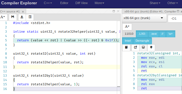
Okay, so let’s look at this rotation code and see if it works as intended, first with XC16. Here’s a 32-bit rotate, both with a general rotate count and also with a rotate-by-1:
pyxc16.compile('''
#include <stdint.h>

inline static uint32_t rotate32helper(uint32_t value, int rot)
{
  return (value << rot) | (value >> ((- rot) & 0x1f));
}

uint32_t rotate32(uint32_t value, int rot)
{
  return rotate32helper(value, rot);
}

uint32_t rotate32by1(uint32_t value)
{
  return rotate32helper(value, 1);
}


''', '-c', '-O1', '-fverbose-asm', '-finline')
_rotate32: neg w2,w3 ; rot, tmp51 and w3,#31,w3 ; tmp51,, tmp52 mov.d w0,w4 ; value, tmp53 .LB9: dec w3,w3 ; tmp52 bra n,.LE9 lsr w5,w5 ; tmp53, tmp53 rrc w4,w4 ; tmp53, tmp53 bra .LB9 .LE9: .LB10: dec w2,w2 ; rot bra n,.LE10 add w0,w0,w0 ; value, tmp54 addc w1,w1,w1 ; value, tmp54 bra .LB10 .LE10: ior w4,w0,w0 ; tmp53, tmp54, tmp50 ior w5,w1,w1 ; tmp53, tmp54, tmp50 return _rotate32by1: lsr w1,#15,w2 ; value,, tmp48 mov #0,w3 ; tmp48 add w0,w0,w0 ; value, tmp49 addc w1,w1,w1 ; value, tmp49 ior w2,w0,w0 ; tmp48, tmp49, tmp47 ior w3,w1,w1 ; tmp48, tmp49, tmp47 return
Argh! Sure, it’s going to give the correct result, but the compiler is following the C code essentially step-by-step, performing exactly what we tell it. I would expect this for rotate32 since the dsPIC instructions for bit rotation don’t operate for a general number of bit rotations, but for rotate32by1 I would have expected some attempt at using RLC if this C code were truly “idiomatic”. It is smart enough to evaluate (-1 & 31) at compile-time, but beyond that, we’re still doing a 32-bit shift left (ADD + ADDC) and then a 32-bit bitwise OR (IOR + IOR) with the most significant bit of the input. This should be a three-instruction sequence rather than a six-instruction sequence, something like
_rotate32by1:
    btst.c w1,#15    ; move high bit into carry
    rlc    w0,w0     ; rotate low word left with least significant bit coming from bit 31 of the input
    rlc    w1,w1     ; rotate high word left with least significant bit coming from bit 15 of the input
    return
So XC16 doesn’t (at least not as of November 2017) know about “idiomatic” bit rotation. (I tried -O3 on my work PC; on my Mac at home I don’t have my own personal copy with -O3 enabled.)
Compiler Explorer: Trust but Verify, Web-Style
I’m not very experienced in other architectures (except TI 28xx DSP, and that knowledge has been decaying for the last five years from lack of use), so to see which compilers recognize the bit rotation idiom, let’s use a nifty tool called Compiler Explorer.
Oh, but first we need to just check if there’s some generally-accepted advice about “idiomatic” bit rotation. I found these reputable sources, all of which confirm the idiom used in the PCG implementation:
- John Regehr’s blog, “Safe, Efficient, and Portable Rotate in C/C++” (2013)
- a forum post on Intel’s website — normally I wouldn’t consider forum posts “reputable” information, but this one links to a bug report in gcc on the subject, and has a reply from someone on the Intel compiler team that says that their compiler recognizes the “idiom”. Of course, Intel’s compiler also provides intrinsics for bit rotation, which are nonportable.
- a Stack Overflow post — again, I don’t consider SO necessarily reputable, but the author of the accepted response has gone to a lot of trouble to cite sources.
Before we look at Compiler Explorer, I need to make sure you realize that C compilers are pretty special, and not just dumb software programs that can’t understand the C equivalent of “high five” and can’t write assembly code as good as I can. Rather than try to make a good counterargument, I will just refer you to this video of Compiler Explorer’s author, Matt Godbolt, giving a talk at CppCon 2017 called What Has My Compiler Done For Me Lately? Unbolting the Compiler’s Lid, which you simply must watch:
OK, now we’re ready to give Compiler Explorer a try on the bit rotation code.
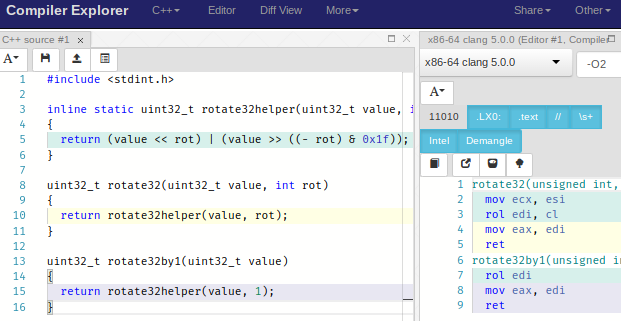
Pow! GCC for x86-64 hit that right out of the park and used the rol instruction. So does clang 5.0, as long as we use -O2:
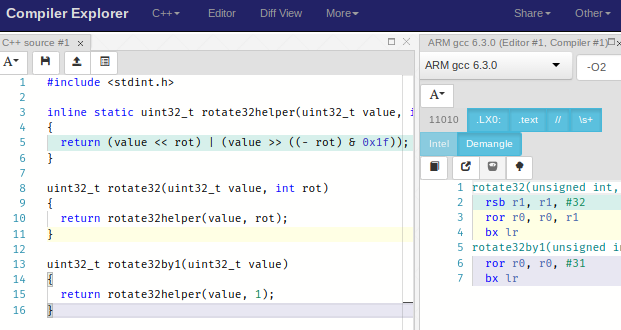
and so does GCC for ARM (interestingly, ARM uses ROR for rotation, not ROL; if you want to perform a left-rotation you have to express it in terms of a right-rotation):
What’s neat about Compiler Explorer is that it’s so fast that you can just try things on the fly. Here’s what it does with my lfsr_step6_noreturn function on gcc 7.2, my last attempt at an LFSR update before turning to inline assembly:
lfsr_step6_noreturn(LFSR_T*):
  movzx edx, WORD PTR [rdi+2]
  mov eax, DWORD PTR [rdi]
  and dx, WORD PTR [rdi+6]
  add eax, eax
  mov DWORD PTR [rdi], eax
  test dx, dx
  je .L1
  xor ax, WORD PTR [rdi+4]
  mov WORD PTR [rdi], ax
.L1:
  rep ret
The clang 5.0 compiler can apparently do a little better, shaving off one instruction — although with modern PC processors, counting instructions is very problematic because there’s all sorts of subtle effects like memory caches and instruction reordering and so forth that can alter the execution time of a function.
lfsr_step6_noreturn(LFSR_T*): # @lfsr_step6_noreturn(LFSR_T*)
  movzx ecx, word ptr [rdi + 2]
  mov eax, dword ptr [rdi]
  add eax, eax
  test cx, word ptr [rdi + 6]
  mov dword ptr [rdi], eax
  je .LBB0_2
  xor ax, word ptr [rdi + 4]
  mov word ptr [rdi], ax
.LBB0_2:
  ret
I’ve tried looking at the other implementations of lfsr_step with Compiler Explorer, and it’s somewhat interesting, but since I have essentially no experience with x86 or assembly, it’s hard to decide which is better. On a PC I probably wouldn’t bother to optimize at all, whereas on the dsPIC there are more serious execution time constraints.
Verify! Don’t Forget to Verify!
Okay, all this optimization-related talk makes me guilty of leaving a discussion of correctness until the end; in general this is backwards — write it first correctly, then optimize if necessary, because, as we all should know from understanding Donald Knuth’s quote on optimization:
We should forget about small efficiencies, say about 97% of the time: premature optimization is the root of all evil.
But on the other hand, no matter when you work on verification, as long as you’re making new changes, verification is always the last thing you have to do. So really the order often works like this:
- Develop proof of concept
- Verify correctness
- Optimize code based on project needs
- Run final verification tests
And as far as the 97% business goes, I had a use case for code similar to this LFSR that executed 8 times in a critical 20kHz control loop, on a dsPIC running at 70MIPS. In that case, each 1 instruction saved is 0.23% of the CPU (160kHz / 70MHz) – not a huge amount, but enough to make me look for easy gains.
At any rate, I have verified the different variant implementations of LFSR update in this article (with very minor modifications for testability) in a public repository, by creating a test harness.
You can run this yourself with MPLAB X, either in the simulator or on compatible hardware — I used an MCLV2 motor control development board I had lying around, which uses the dsPIC33EP256MC506, but aside from the oscillator setup, which is processor-specific, it will work on any PIC24 or dsPIC device.
Essentially what it does is to run all of the LFSR update variants on different state structures a bunch of times, and every 16 iterations, it compares against expected output. We’re essentially verifying the state against the coefficients of \( x^{16}, x^{32}, x^{48}, x^{64}\ldots \) in the quotient ring represented by the degree-31 primitive polynomial 0x80000009 (\( x^{31} + x^3 + 1 \)).
from libgf2.gf2 import GF2Element

e = GF2Element(1,0x80000009)
for k in xrange(16,161,16):
    print '  0x%08x,   // x^%d' % ((e<<k).coeffs, k)
0x00010000, // x^16 0x00000012, // x^32 0x00120000, // x^48 0x00000104, // x^64 0x01040000, // x^80 0x00001248, // x^96 0x12480000, // x^112 0x00010010, // x^128 0x00100012, // x^144 0x00120120, // x^160
The test harness looks like this:
#define NVARIANTS 8
LFSR_T lfsr[NVARIANTS];
const uint32_t polynomial = 0x80000009;
volatile uint32_t black_goo = 0;
/* this is here to confound the compiler
   and allow us to put breakpoints somewhere */

int kvisible;
int nfailures;

void run_tests(void)
{
    int i,k;
    const uint32_t expected_results_every16[] = {
        0x00010000,   // x^16
        0x00000012,   // x^32
        0x00120000,   // x^48
        0x00000104,   // x^64
        0x01040000,   // x^80
        0x00001248,   // x^96
        0x12480000,   // x^112
        0x00010010,   // x^128
        0x00100012,   // x^144
        0x00120120    // x^160
    };

    black_goo = 0;
    nfailures = 0;

    for (i = 0; i < NVARIANTS; ++i)
    {
        lfsr_init(&lfsr[i], polynomial);
    }

    for (k = 0; k < 160; ++k)
    {
        kvisible = k;

        lfsr_step1(&lfsr[0]);
        lfsr_step2(&lfsr[1]);
        lfsr_step3(&lfsr[2]);
        lfsr_step5(&lfsr[3]);
        lfsr_step6(&lfsr[4]);
        lfsr_step7(&lfsr[5]);
        lfsr_step8(&lfsr[6]);
        lfsr_step9(&lfsr[7]);

        ++black_goo;
        if ((k & 0x0f) == 0xf)
        {
            ++black_goo;
            uint32_t expected = expected_results_every16[k>>4];
            for (i = 0; i < NVARIANTS; ++i)
            {
                if (lfsr[i].state.state32 != expected)
                    ++nfailures;
            }
        }
    }

    black_goo = 1;
}
The black_goo lines use a volatile variable to prevent compiler optimization and allow putting a breakpoint on those lines. After running this, the nfailures variable is zero; if I tweak the code to create an intentional error then it becomes nonzero. So the LFSR update code works correctly! Well… to be more pedantic, it works correctly for one set of inputs iterated enough times to gain confidence that I haven’t made any stupid mistakes. That’s about the best you can do aside from careful engineering and review — or the use of formal program verification techniques, which are above my pay grade.
(For what it’s worth, I didn’t get my code 100% right the first time; the structure was fine but I had made some minor errors that were an easy fix once I ran the test harness to uncover them. So verification really is important!)
Wrapup
- Today we looked at a number of different implementations of an LFSR update on the dsPIC33E, some of which are faster to execute than others:
- Our first attempt took 29 cycles not including call and return
- We were able to reduce it to 13 cycles in pure C
- We were able to reduce it to 8 cycles using some simple helper functions in inline assembly.
- We discussed the idea of “idiomatic C” and its implications for bit rotation
- We looked at Compiler Explorer, an online website for examining the assembly output of the compiler
- We showed how to verify the different LFSR implementations using a test harness.
Next time we’re going to jump back into the theoretical world and look at some matrix methods for analyzing LFSRs.
© 2017 Jason M. Sachs, all rights reserved.


- Comments
- Write a Comment Select to add a comment
To post reply to a comment, click on the 'reply' button attached to each comment. To post a new comment (not a reply to a comment) check out the 'Write a Comment' tab at the top of the comments.
Please login (on the right) if you already have an account on this platform.
Otherwise, please use this form to register (free) an join one of the largest online community for Electrical/Embedded/DSP/FPGA/ML engineers:


