


Making a connection 1
In order for your system to control devices, you must be able to connect it to those devices.
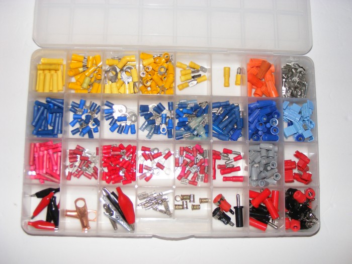
Besides different sizes based on wire size, there are a few different styles of connectors that can be used. There are also weather-resistant terminals that can be used if needed.
Ring
(Parks, 16)
- used for circuits that you don’t want to become easily disconnected
- ground wire attached to a stud
Push-On
- can be used on relay terminals
(Parks, 18)
- could be used to attach two wires together
(Candela, 45)
- use white lithium grease in connector to maintain good connection
Bullet
(Parks, 16)
- used to connect two wires end to end, but allow for disconnecting
Butt
(Parks, 16)
- used to join two wires end to end
Fork
(Parks, 16)
- allow for easy removal of a wire from a terminal strip
Alligator Clips
- used for temporary connections
- allow for attaching a test lead to a point
Once you have found a suitable terminal, there are a couple of ways to attach it to the wire.
Solder
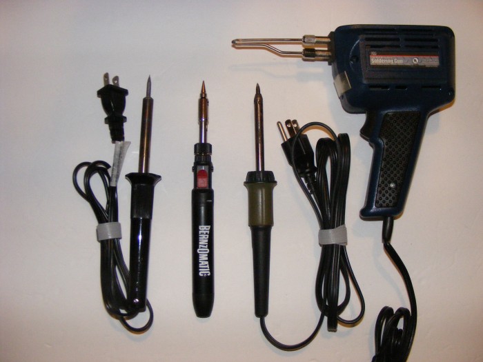
- if you are also going to crimp the connector, crimp first, then solder
- take care to not melt the wire insulation
- larger terminals, like 2 gauge, may be soldered
Caution:If you are using a butane soldering iron, remember that open flames can react spectacularly with certain objects and invisible gases.
You will want to tailor the size of the soldering iron to the size of the terminal.
Crimp
(Parks, 16)
- after crimping, you should tug on the wire and connector to make sure it is not loose
(Candela, 43)
- Inexpensive connectors have seams.You must take care that the seam doesn’t open up when it is crimped.
(Candela, 46-47)
- strip ¼” of insulation from wire
- twist stripped end clockwise to align strands
- push terminal on so 1/16” wire sticks out
- orient tool so that stake is opposite of seam
- squeeze tool to make crimp
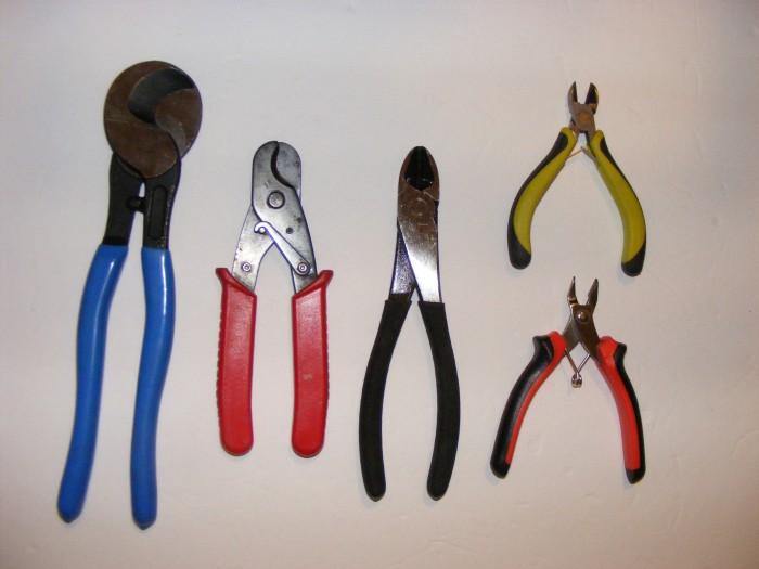
Wire cutters come in various shapes and sizes.Shown at left are cable cutters which are needed to make clean cuts in larger wires, and also to provide enough leverage to cut them.Middle and top right are side cutter pliers, which are useful for cutting smaller wire.Bottom right are flush cutters, which are useful for trimming wires close to a circuit board.
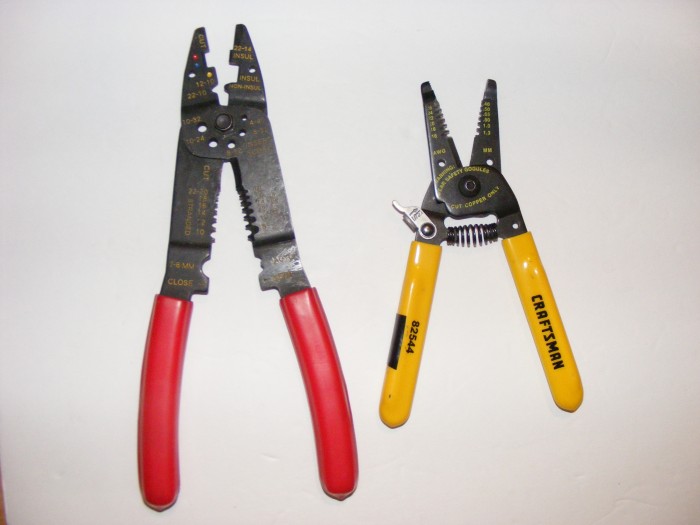
Wire strippers remove the insulation from the wire without nicking or damaging the conductor.Using a knife can score the copper conductor and weaken it.
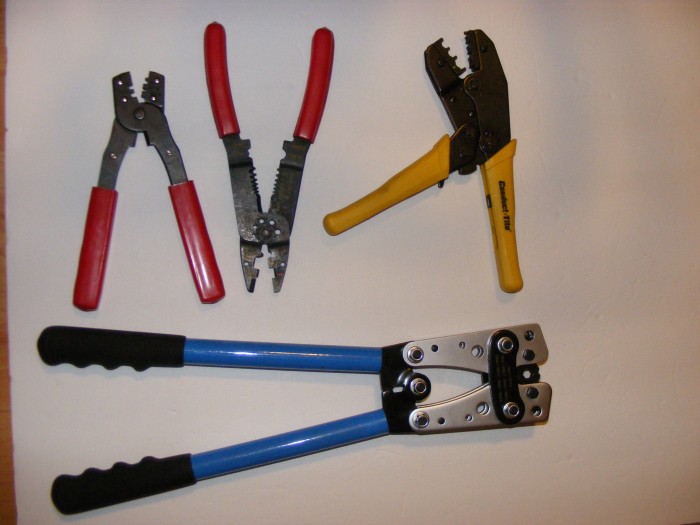
Crimping tools come in sizes relative to the terminal.Top left are useful for RS-232 ends.The two to the right are used for 10-20 gauge terminals.The pair at the bottom are used for up to 0 gauge wire.There are also hydraulic and hammer operated crimpers for the large terminals. They are needed for large gauge wire used to connect automotive-type batteries to power the system.
Generally used color coding for insulated terminals
Red:18 to 22
Blue:14 to 16
Yellow 10-12
(This color coding is not absolute, and larger connectors may also use these colors.)
Works Cited
Candela, Tony. Automotive Wiring and Electrical Systems. CarTech, 2009.
Martin, Tracy. Electrical Systems Diagnosis and Repair. National Street Machine Club, 2008.
Parks, Dennis W.Automotive Wiring – A Practical Guide to Wiring Your Hot Rod or Custom Car.Motorbooks, 2011.


- Comments
- Write a Comment Select to add a comment

if you are also going to crimp the connector, crimp first, then solder
No, these are mutually exclusive methods of achieving an electrical connection. A good crimp achieves a gas-tight electrical connection, typically on stranded copper wire. Soldering, especially with stranded wire, produces stress concentration points, and solder (aside from silver solder) has a much lower conductivity than copper so if you can get a good crimp, there's no real value to adding a solder joint.
Some more good information here: https://www.eevblog.com/forum/projects/crimp-*and*...

Good point.
Crimping the connector is the best way to go. Most automotive connectors are crimped and are subject to harsher conditions than most systems will ever see.
I have soldered a few terminals too, because I couldn't get a good crimp.
Do not stick a piece of solder in the connector with the wire and then crimp it, you will not get a good crimp and will probably have trouble melting the solder.
To post reply to a comment, click on the 'reply' button attached to each comment. To post a new comment (not a reply to a comment) check out the 'Write a Comment' tab at the top of the comments.
Please login (on the right) if you already have an account on this platform.
Otherwise, please use this form to register (free) an join one of the largest online community for Electrical/Embedded/DSP/FPGA/ML engineers:

