


The Least Interesting Circuit in the World
It does nothing, most of the time.
It cannot compute pi. It won’t oscillate. It doesn’t light up.
Often it makes other circuits stop working.
It is… the least interesting circuit in the world.

What is it?
About 25 years ago, I took a digital computer architecture course, and we were each given use of an ugly briefcase containing a bunch of solderless breadboards and a power supply and switches and LEDs — and a bunch of 7400 LS-series logic ICs in DIP packages. We were required to hook these up with 22-gauge solid wire to implement a “computer” based on circuit diagrams we were given at the beginning of the semester. It was a lot of work, figuring the right length of wire, stripping the ends about 6mm, and shaping it to run from one hole in one area of the breadboard over to another area. Repeat about two or three hundred times, run some tests to make sure it works as intended, and hope you don’t have some nasty mistake that would require you to tear the whole thing apart.
The DIP packages were pretty boring; hook up 5V in the upper right corner, hook up GND in the lower left corner, connect a bunch of other wires. We had a few other analog things to add to it — unavoidable interlopers in a digital world, which nobody wanted to talk about in this wonderful digital electronics course: 0.1μF bypass capacitors across the power supply pins of each of the DIP packages, some resistors and capacitors to use with a monostable multivibrator (74LS221, I think…) as a clock source. And then this:
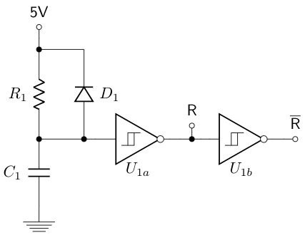
The R and R̅ nodes stood for reset, and they were distributed across the “computer” to a couple of places. I don’t remember the exact values of \( R_1 \) and \( C_1 \) — let’s just say it was 100KΩ and 1.0uF, for a time constant of 100 milliseconds. The idea is that when you turn on the power supply and 5V comes up, the input voltage at the Schmitt trigger \( U_1 \) takes some time to come up to the logic threshold, somewhere roughly around one time constant, at which point R switches from high to low, and R̅ switches from low to high. Essentially, you get an active high pulse at R and an active low pulse at R̅ for a time that is long relative to other electronic stuff, but seems very short to a person.
The diode \( D_1 \) is there to pull charge out of \( C_1 \) quickly when the power supply turns off. If you get rid of \( D_1 \), and the power supply glitches very quickly down to zero before coming back on, there’s a chance that the capacitor \( C_1 \) will stay charged and the reset pulse is too short or even nonexistent.
If you like, you can put a momentary push-button switch in parallel with \( C_1 \) to force a manual reset pulse.
Why do we need a reset pulse? We want things in our system to go to a well-defined state during a power supply reset. Digital flip-flops, used in most sequential logic circuits, have two stable states, 0 and 1, and when the power comes on, you might see 0 some of the time and 1 some of the time. Which will it be? We don’t know. The flip-flop output depends on random chance. Suppose you had a 3-bit register that went to a demultiplexer that asserted one of 8 active chip select signals:
000= LED1001= LED2010= SD card write011= UART100= wireless radio101= solenoid connected to trigger of semi-automatic rifle110= audio speaker111= vibrating motor
You turn the thing on, and every once in a while, the register comes up as 101 and the semi-automatic rifle goes BANG. Oops. Probably not a good idea.
Having a reset pulse allows you to do two things:
- Initialize the register to a known state, like
000for LED1 - Disable the demultiplexer during the reset pulse.
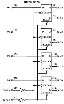
The first of these, initializing the register to a known state, typically happens as an asynchronous clear input to a flip-flop. No matter what, if the clear input is active, any noninverting output goes to 0 and any inverting output goes to 1. In the 74LS175, the clear pin is active low, so we could hook it up to the R̅ line so that during the reset pulse, all the flip-flops are reset to the zero state, and its Q outputs are low and its Q̅ outputs are high.
The second of these is typically implemented by a gate input; in the 74HC138, for example, we have 8 outputs O0-O7, a 3-bit address input A2A1A0, and three enable gate inputs, one (pin 6) which is active high and two (pins 4 and 5) that are active low. We could ground pins 4 and 5, and hook up pin 6 to the R̅ line so that during the reset pulse, pin 6 is pulled low and none of the outputs are asserted.

All reset behavior basically boils down to these same two actions:
- Initialize registers to desirable known states
- Temporarily disable outputs
Sometimes the “disable outputs” means put them temporarily into an inactive state (low for active-high signals and high for active-low signals), in other cases it means put them into a high-impedance or “tri-state” behavior so that some other circuit can drive the same line. And in some circumstances, it means temporarily activate a “safe” behavior, like a pullup current source or turning on a MOSFET to discharge a capacitor.
In case of a microcontroller, there is typically a reset input, almost always active-low, that does the following:
- Reset all special function registers to their power-on values. (usually zero, but you need to read the datasheet; in the case of the dsPIC33EP256MC506, for example, the
CORCONregister is reset to0x0020, whereas the interrupt flagsIFSxand interrupt enablesIECxare all reset to zero.) - Set all general-purpose outputs to a high-impedance state.
- Set the program counter to jump to a reset vector, so that when the reset pulse ends, code starts executing from a predetermined address, often the zero address.
In most microcontrollers, the RAM content is not reset, so that if you get a reset while the device is still connected to a valid power supply voltage, the RAM will retain its previous state and the embedded system in question can access information on what it was doing before the reset. This has to be done with some care, however, and when programming in C, any access to normal C variables must be done before the normal C startup routine executes, since this is responsible for initializing program variables. (The C compiler’s contract is to make sure any variables of static storage duration are initialized before entering main(); for C99, take a look at N1256 sections 5.1.2 and 6.7.8)
Sometimes it is also possible to declare a program variable as “persistent”, so that the C startup routine doesn’t initialize that particular program variable, and the value on power-up will be indeterminate, unless specifically indicated by the microcontroller’s datasheet. (Look carefully! Don’t assume user RAM gets initialized to all-zeros at powerup.) The C language does not have a standard way of doing this, so it will vary between language implementations. In Microchip’s XC compilers, for example, the appropriate syntax is usually either
__persistent int foo;
or
int foo __attribute__((persistent));
This topic is fairly dull, and often skipped over in favor of more exciting aspects of microcontrollers, like all those goodies in the sections on peripherals.
We now turn to one of the most important questions in circuit design in the embedded world, which is also fairly dull, and as a result is frequently at risk for design errors:
What Should You Use for Reset Circuitry When Designing Embedded Systems?
The answer to this question, along with many others in engineering, is it depends.
Having no reset circuitry is inappropriate with digital circuitry, so if you’re using discrete 7400 series logic gates with registers, you’ll end up with unpredictable results, unless you clear them during a reset pulse.
The circuit I showed earlier is also inappropriate in general circumstances:
It worked fine in an academic setting on known equipment, but there’s a reason this won’t work well for general-purpose use, and it’s not the poor tolerancing on reset pulse width — if reset pulse can vary by a factor of two or three over temperature and from part to part, that’s usually no big deal. 50 milliseconds, two hundred milliseconds, no big deal in most cases.
Imagine that the 5V line in this circuit increases from zero to 5V very slowly, say over several seconds. What voltage does it reach when the reset pulse starts and ends? We don’t know, and that’s bad, because different circuits in our system can start doing things at different voltages. If the 3-bit register, demultiplexer, and solenoid connected to the trigger of the semi-automatic rifle all start working at 2.5V, but the reset pulse doesn’t start until 2.8V, we have a problem.
So the rigorous thing to do is to use a reset circuit that has well-defined behaviors at particular voltages. Let’s take a look at a voltage scale diagram with a couple of important thresholds:
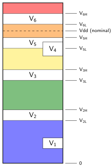
This applies to any circuit, but for the moment think of a microcontroller that runs on Vdd = 3.3V nominal, like a dsPIC33EP256MC506. The voltages \( V_2, V_3, V_5, \) and \( V_6 \) are thresholds with some tolerance range, so that they can vary from part to part and vary over temperature:
-
\( V_2 \) — startup voltage. The low end of this tolerance range, \( V_{2L} \) is the highest voltage so that nothing in the circuit will operate. The high end of this tolerance range, \( V_{2H} \) is the lowest voltage at which everything in the circuit may do something. Below \( V_{2L} \) (the blue region) we can consider the circuit “off” for all practical purposes. Above \( V_{2H} \) (the green region) it is operating with indeterminate behavior. Between \( V_{2L} \) and \( V_{2H} \) it may be “off” or it may be operating with indeterminate behavior; we just don’t know. The exact threshold may vary from part to part or over temperature, and it may be a different threshold for different elements in the circuit. If we have an ADC and a PWM generator, the PWM generator might start doing something in the 2.0 - 2.4V range and the ADC might start doing something in the 2.1-2.6 range. These ranges usually aren’t specified by the manufacturer.
-
\( V_3 \) — “functional” operation voltage. At some point within this range, there is a threshold above which the circuit will be functionally correct but may not meet all the specifications. In the dsPIC33EP256MC506 datasheet, this is described as follows (see note 1 of DS70000657H page 411):
Device is functional … but will have degraded performance. Device functionality is tested, but not characterized. Analog modules (ADC, op amp/comparator and comparator voltage reference) may have degraded performance.
What this means is that above \( V_3 \), nothing “bad” is going to happen; the device isn’t going to start asserting its outputs with signals representing “REDRUM! REDRUM! REDRUM!” in Morse code. ADC specifications may not be met, so there might be larger-than-average gain or offset error, and it might take longer to get a valid ADC signal… but the basic state machine of the device is going to function properly. The CPU will execute digital logic correctly. Above the high end of this tolerance range, \( V_{3H} \), is the yellow region, where “functional” behavior is guaranteed.
-
\( V_5 \) — minimum guaranteed proper operation. At some point within this range, there is a threshold above which the circuit will meet all its specifications. The high end of this tolerance range, \( V_{5H}, \) is the lowest guaranteed operating voltage specified in the datasheet; for the dsPIC33EP256MC506 this is 3.0V.
-
\( V_6 \) — maximum guaranteed proper operation. At some point within this range, there is a threshold above which the circuit may not meet all its specifications. The low end of this tolerance range, \( V_{6L} \) is the highest guaranteed operating voltage specified in the datasheet; for the dsPIC33EP256MC506 this is 3.6V.
The orange region between \( V_5 \) and \( V_6 \) represents guaranteed proper operation within specifications; the red region above \( V_6 \) represents operation out of spec, where portions of the circuit do not work properly. (And not shown is the absolute maximum voltage; operation above this voltage can cause irreversible damage to the circuit due to voltage stress, and the manufacturer can no longer make any guarantees about the device, even if voltage later resumes operation in the normal range.)
To summarize:
- \( 0 \leq \) blue \( \leq V_2 \) = off
- \( V_2 \leq \) green \( \leq V_3 \) = indeterminate operation, voltage too low and out of spec
- \( V_3 \leq \) yellow \( \leq V_5 \) = functional operation, voltage low and out of spec, but normal digital state machines will work
- \( V_5 \leq \) orange \( \leq V_6 \) = guaranteed proper operation
- \( V_6 \leq \) red = indeterminate operation, voltage too high and out of spec
Because each threshold has a tolerance range, within the range is a sort of gray area where desired/undesired behavior can coexist across a population of parts, somewhat like Schrödinger’s cat. Each individual part at a given time has a specific threshold, although I mentioned earlier that in complex circuits like modern microcontrollers, different subcircuits will have different voltage thresholds.
And unfortunately, there won’t be specifications for many of the voltages shown on the diagram. \( V_{5H} \) and \( V_{6L} \) always will be specified, but the rest generally aren’t. For the dsPIC33EP256MC506, \( V_{3H} = \) 2.65V and in the yellow range, the “Device is functional … but will have degraded performance” advice applies.
The other two thresholds, \( V_1 \) and \( V_4 \), pertain to the reset circuit.
-
\( V_1 \) — startup voltage of the reset circuit. We always want \( V_1 \leq V_2 \), so that the reset circuit is the first part of the system to start operating as the supply voltage comes up.
-
\( V_4 \) — reset voltage threshold. Between \( V_1 \) and \( V_4 \), the circuit should be providing an active reset signal to hold our system in reset. Once the supply voltage exceeds \( V_4 \), the reset signal should continue for some minimum time, and then de-assert.
The proper value of a reset threshold is a bit tricky to choose, and depends on who’s choosing it and the consequences of that choice.
For example, Microchip gives the range \( V_{4L} = \) 2.65V and \( V_{4H} = \) 2.95V for the dsPIC33EP256MC506’s built-in brown-out reset (BOR) circuit. This guarantees that \( V_{4L} \) is in the yellow range, so that the BOR reset will ensure that a reset pulse is present in the green range, preventing indeterminate operation. But the BOR reset threshold is also guaranteed to be below the normal range of operation (orange region). From a semiconductor’s standpoint, this is a good thing. We can always run within the full 3.0 - 3.6V range with no chance of an errant reset due to undervoltage. What we give up, however, is that there is going to be some range of voltages above the BOR threshold but below the minimum guaranteed operation voltage of 3.0V. Let’s say the BOR threshold happens to be 2.9V for one particular part at a certain temperature. Then we have this range of 2.9V-3.0V, where the BOR does not occur, some of which may be in normal operation, and some of which may be in the “functional” operation region of reduced analog performance.
As a customer, I might want to guarantee normal operation when not in reset. This means I could choose an external power supply supervisor and reset generator like the MCP809-315 with threshold \( V_4 \) that has a tolerance band 3.0V - 3.15V, and use its RST output as the reset input for a microcontroller.
- below 3.0V the reset generator will hold the microcontroller in reset
- between 3.0V and 3.15V the reset generator may hold the microcontroller in reset
- above 3.15V the part will not hold the microcontroller in reset
This still allows me to use a 3.3V nominal power supply as long as I can guarantee its output is 3.15V minimum, which is about 4.5% below nominal.
I might also decide to use a power supply supervisor with this tolerance range, but for only a critical part of my system, rather than the microcontroller. For example, if I had a motor controller, I could use the power supply supervisor’s RST output to turn off gate drive signals to power transistors. I could also feed this signal into a general-purpose input to the microcontroller, so the microcontroller could tell when this low-voltage condition occurred.
I could also rely on the internal BOR in the dsPIC33EP256MC506, but then I’d have to accept that operation in the “functional” range (yellow region, below spec, reduced analog performance) may occur without any reset.
You could argue, “well, we’ll just put a voltage reference onto an ADC pin and monitor the supply voltage in software.” And that would probably work. Connect up a ±1% voltage reference around the 1.2V silicon bandgap, like a TLV431, and use the AVdd voltage as the fullscale limit for the ADC; go through the tolerance analysis of the ADC, and determine some maximum ADC reading above which we can safely assume that the voltage is between, say, 3.0V and 3.08V, based on the tolerance analysis. (It’s always going to be wider than the tolerance of the voltage reference because the ADC is an additional source of error.)
There are a few holes in this approach, however:
- ADC readings form a sampled-data system. We aren’t looking continuously at the supply voltage, so if there are voltage spikes between ADC readings, we’d miss them
- We’re depending on the ADC to help sense a supply voltage below which the ADC might not work with full accuracy. So there’s a circularity problem here, and we can’t guarantee it will work with enough accuracy to work properly.
So a simpler dedicated circuit with a comparator would work better. Some microcontrollers do have on-board dedicated comparators. It’s a tough call, though — Moore’s Law allows using smaller process geometries for digital electronics to reduce area and costs, but this benefit doesn’t apply to precision analog electronic circuits like op-amps and comparators, which look very large compared to the average logic gate on modern microcontrollers. As a result, the op-amps and comparators put onto microcontrollers may be specialized to work well under a limited set of conditions. A dedicated comparator IC will have better performance specs than one shoehorned into a microcontroller, but you will pay more for having an external package.
Anyway, you get the picture — use a voltage reference to detect an undervoltage condition and make sure your critical circuit isn’t operating until the supply voltage is valid.
Most voltage supervisor ICs also include a minimum pulse width, so that if you have an undervoltage glitch on Vdd for a few hundred nanoseconds, you’ll get a reset pulse of at least a few milliseconds. The MCP809-315, which I cited earlier, has a minimum pulse width in the 150ms - 700ms range, so if that’s too long for you, you’ll have to find something else. The NCP302 has an extra pin that you attach a capacitor to set the pulse time.
In any case, choosing the right circuitry is an exercise for the reader; there’s no one circuit that works in all cases.
Wrapup
We talked about reset pulse generator circuits. They’re not very exciting, but they’re rather important.
You’ll want to make sure that for these circuits:
- the reset pulse becomes active starting at a lower voltage than any other system becomes active (including voltage tolerances!)
- the reset pulse does not become inactive until the voltage reaches a “safe” voltage sufficient for the rest of the system to work properly (including voltage tolerances!)
- the reset pulse lasts for some specified minimum time that is adequate for the system
- you use them to hold critical components in a reset state that disables any critical outputs, and sets any sequential logic to a well-defined state
As for me, I don’t always design electronic circuits… but when I do, I use a carefully-designed reset pulse generator.
Stay careful, my friends!
© 2018 Jason M. Sachs, all rights reserved


- Comments
- Write a Comment Select to add a comment
Well well well, I will say after reading this, which I was unsure of in the beginning. LOL But being the most interesting man picture you posted intrigued me. :) You just solved
a problem my engineers have been working on. It was a lithium ION under-voltage issue. After reading
this I sat down with my team and brought this up. Well not only did it make me look smart it looked like
I was staying current with current IOT tech. It also solved a problem they weren't looking at fully.
Just had them recreate the PCB and run some tests and wa laa. :). Jason it is always an honor to read your posts and articles keep up the fantastic work.
And they thought just because I was retired I wasn't productive LOL. Well supposed to be retired. not sure that's entirely possible. I love this stuff.

Ohhh. I would say watchdog. But yes. You found one even more boring. And made an interesting article. Thanks.
The fact it is the least interesting circuit is in itself interesting... just say'n

Hi Jason.
That was both an educational and fun read. Good job!
I liberated it from a math prof. Substitute "number" for "circuit". BTW, he was a number theorist. Jobs could not hold a candle as far as reality-distortion fields when compared to number theorists. I had two of them in university. Key indicator - their ties would turn backwards all by themselves. Some of the weirdest people you will ever meet. Friggin brilliant. One lived on Euclid Ave in LA.
To post reply to a comment, click on the 'reply' button attached to each comment. To post a new comment (not a reply to a comment) check out the 'Write a Comment' tab at the top of the comments.
Please login (on the right) if you already have an account on this platform.
Otherwise, please use this form to register (free) an join one of the largest online community for Electrical/Embedded/DSP/FPGA/ML engineers:


