


RMS calculation over one cycle 50/60Hz
My question is based on this paper: http://www.eletrica.ufpr.br/edu/artigos/CIL22-012_...
It says:
Due the characteristics of AC energy, voltage and current waveforms mean are zero; however, during abnormal operation fluctuations may occur or oftentimes the offset error introduced by transducers must be accounted for the correct characterization of the energy. These calculations are performed with a digital processing, using sequential samples with sample frequency equal to N times the AC frequency, nominally 60 Hz or 50 Hz. If the value N exactly matches the ratio between sample frequency fs = 1/Ts and AC frequency f = 1/T, there are only quantization errors due to finite length of bit number of samples. If, however, the ratio fs/f is not an integer value, what occurs most of the cases, more errors are introduced (Mesrobian et al., 1991).
So in my case for one cycle I can't have an integer N that matches both 50 and 60 Hz and possible fluctuations. In the microcontroller, the plan I have is to set an ADC triggered by a timer for a fixed sampling frequency, say 6 kHz.. I can also use DMA or double buffer approach if needed. The formula for RMS proposed in the paper is
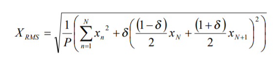
Do you think this is a right approach? Other suggestions are welcome. I'm not a software/firmware guy so basically I'm also asking for some help on how to code this equation in the microcontroller, like a pseudocode.
If you sample by 6kHz, then your sample rate actually is an integer multiple of both 50Hz (6000/50=120) and 60Hz (6000/60=100).
The mains frequency is usually changing slowly (those hundred ton turbines and generators have a considerate inertia) so you can measure and track the frequency and use a digital PLL (that is, vary your ADC trigger timer's count) to match it. Even if your micro is running on a very slow clock, say 2MHz, you can tune your sampling period in 500ns steps, which at 60Hz means 30ppm precision. Although on a 2MHz core you will likely to run out of processing power way before the sampling time resolution becomes a problem (you have 333 clocks between samples). On a more realistic but still conservative scenario, say an ARM core running at 30MHz you can tune your ADC within 2ppm of an integer multiple of the mains, surely enough?
You may want to look at two of my blogs
There are some interesting comments as well, so remember to scroll down.
And a series of 3 on measuring the RMS internal to a PSoC5 micro.
Measuring an RMS value on a PSoC5, Part 1: Signal Acquisition
Measuring an RMS value on a PSoC5, Part 2: Squaring a Reading
Measuring an RMS value on a PSoC5, Part 3: Square Root and Result
One way to deal with both 50Hz and 60Hz is to use a frequency multiplier, such as a PLL based one. The output frequency of such a circuit is in sync with but N-times of the input frequency, which will be the sampling clock for the signal you need to measure.
Another hardware based solution is to use the so-called RMS to DC converter, if the budget allows. ADI has this kind of device available.

Hi there,
It is essential to capture the buffer with the whole number of single cycles of a sine wave. No matter where you start to sample the waveform. Thus in the case of 50Hz wave you would have N x 20 ms where N is a whole number. 6kHz of sampling frequency and basic RootMeanSquare formula would do the job.
Cheers,
Adam.
If I'm sampling at 6 kHz, and let's say I take 200 samples, that is 2 cycles of 60 Hz and 1.7 cycles of 50 Hz. Do you think this can yield good RMS estimation? Another point is that I don't need much precision results, even integer RMS would be OK.
1. The more N is the less error is introduced in RMS calculation if you really do not know by any measures (e.g. zero crossing intervals) which frequency of the signal tou are dealing with and you need to estimate 60 Hz and 50 Hz RMS-es of both sinewaves simulteneously..
2. I case of limited size of the buffer, why not to sum squared samples constantly, count #of_samples and calculate the division and squqre root whenever N x 20 ms equals (or almost equals) M x 16,7 ms where both N and M are the whole numbers?
3. It is definitely worth checking the error of RMS estimation of any method from different #of_samples and different waveforms in kind of matlab-like freeware.
As others have pointed out, to measure in one cycle you need to take account of the actual, rather than nominal frequency. But there is a deeper point here, why do you want to measure over one cycle ? If you think that successive cycles might be different are you sure that the differences span exactly one cycle ? Do you really need 50 or 60 updates per second ?
It has been suggested that you could trim the sampling rate to match the incoming frequency but this may be difficult - if you are sampling at 6ks/s better just to adjust the number of samples per cycle by establishing the zero crossing points of the signal. You'll need to filter the signal before looking for the crossings to get minimal jitter and you will need to capture a lot more than 1 cycle to be sure of the required three zero crossings in the measuring period.
MK
I don't have zero cross detection in hardware. What you suggest could be an option in the firmware. The reason I want one cycle RMS is because I need fast response. Can be 2 cycles. But as I said above, since I'm sampling at 6 kHz, and let's say I take 200 samples, that is 2 cycles of 60 Hz and 1.7 cycles of 50 Hz. I don't need much precision results, even integer RMS would be OK. I don't have much experience on this so I don't know how accurate results will be considering any slight frequency variation
As Kocsonya has said, with 6kHz sample rate, you get integer multiples for both 50Hz and 60Hz. For 50Hz, you will need to collect 240 samples instead of 200 to cover two cycles, then you should get comparable accuracy for both frequencies. Sure you will need to change the buffer size. If you don't like to do that, then the sample frequency has to be changed based on the signal frequency. Either way, something needs to be changed in order to get consistent performance.


