


Reading Response Bytes using SPI
I am new to this forum and have joined hoping to seek some answers for challenging problems and also make future contributions to the knowledge base.
I am trying to configure a Si4455 RF chip from TICC3200 using #SPI, and having a bit of trouble with reading the appropriate response bytes from the Si4455. I have followed the sequence as explained in datasheet, to read response from the Si4455. As mentioned in the datasheet w.r.t Fig below, i.e. Make CS low, send API command followed by parameters depending on the command, once this transaction is over make CS high.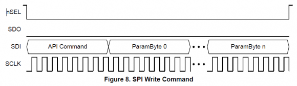
And I have also ported functions from the siliconlabs demo example, that performs the read operations as shown in the Fig's below.
Here is also a link to the Si4455 datasheet Si4455 Datasheet
I have ported functions from SiliconLabs Si4455 demo examples to be compatible with CC3200, which sends command as well as reads response bytes from Si4455. The problem is, I always receive the response bytes as 0xFF, provided I am following the rules of communication as explained in the datasheet. I have searched online and have asked support regarding this question in another forum too, but hardly getting any reliable solutions or none. Please click on the link below where I have put up the code and explained the problem w.r.t to the code in detail .
Here is the link to my post on another forum Link to Code and Explanation
And, is there any minimum SPI bus speed I have to set up in order to effectively communicate or get valid response from the Si4455?. Because at present I am using 100 KHz
I'd appreciate, If anyone can take some time to check on my code, logic or provide some expertise in solving this issue.
Regards
VD

Just looking at the flow chart you show (wait for ff, then read response) and considering that you get ff back from the part makes me think things may be working. You don't mention what, if any, response bytes you get after the ff. Have you checked to see if valid bytes are received?
Since you are running the SPI at only 100KHz (relatively slow for SPI), it may be that you won't see the 00. You would get 00 before the ff only if the results weren't ready.
Now, I haven't read the data sheet and haven't worked with the part. My comments are just based on experience with SPI on other devices.
HTH.
I need to get the chip interrupt status response bytes i.e.8 bytes after sending the GET_INT_STATUS command i.e. 0x20 followed by its parameters.
First I send the command followed by the parameters as depicted in the first figure. The sequence is, Make CS Low-->Send Command (0x20)-->Send 3 Parameters-->Make CS High. I have checked the SCLK, CS and DataOut signals on DSO and it works fine.
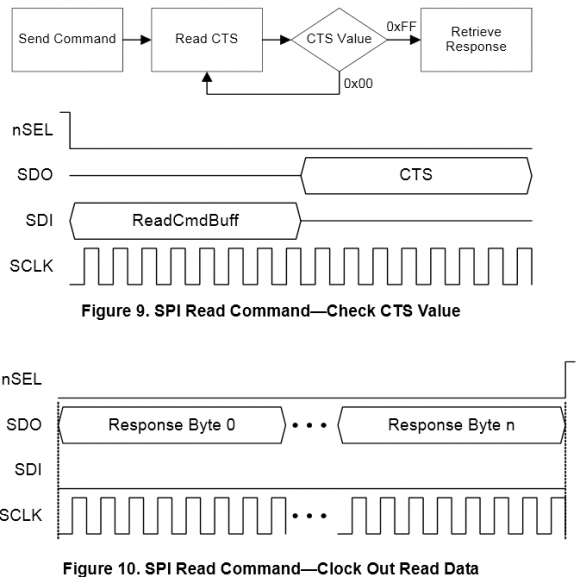
Next, I need to read the response bytes w.r.t the command and parameters I sent in the previous step after checking for CTS. This is how I do it w.r.t figure 2. The sequence are as follows:
Make CS Low-->Send CTS command (0x44) -->Wait till 0xFF is received--> If 0xFF is received--> Immediately Read 8 bytes from the SDO pin of Si4455--> Make CS High.
For the above operation, I have checked in debug mode as well as by probing to the CRO, I don't receive any valid response bytes from the Si4455. And when the CC3200 does not see any data on the SDO of Si4455, it just fills the response array bytes with 0xFF. And this is what I have been getting.
And, I am not sure, if I have to maintain a minimum SPI bus speed to effectively receive response bytes from Si4455, as in the datasheet, it only mentions that Si4455 can operate a speed upto 10MHz. However, I am going to increase the bus speed to 1MHz and give it a try. I know this does not make sense and it has to also work for 100 KHz, but I am running out of ideas and could try every last bit I have got.
OK, here are a couple of thoughts to find the problem. SPI is generally pretty simple, but there can be stumbling blocks.
First, are you sure the part is getting the commands from SPI ok? That is, is there a simple command you can send and verify that the part responds? Perhaps toggle a GPIO pin? Or some such simple thing. You just want to verify the SPI communications is OK.
What is the TICC3200? I couldn't find it on Digikey. If the SPI is configurable, make sure the SPI timing of clock edge to data is correct. SPI has 4 possible configurations. Do you have the right one?
How do you do the data transfer for the expected response? My experience with SPI is that you have to send a byte to get a byte, but I'm not sure that your chip requires that.
BTW, the Si4455 looks like a cool chip! Please post results of your experiments here.
2)Timer on the si4455 is set passed the time allowed so no response and the bit is not populated(not familiar with si4455)
3)or you werent esd grounded when you first put the IC in and now it's not a coherent electronic component now. (he can check this) with an meter or oscilloscope. again im not familiar with si4455, and im not a certified genius or even a wanna be. but this were I would start.

I mentioned your question on Twitter and someone tweeted the following in case this could be helpful to you:

Hi stephaneb,
I am unable to upload the images. Can you please assist me on this.
Regards
VD
What happens when you try to upload images? You can usually drag and drop the image directly in the reply box or click on the upload image button.
I tried both. When I try to upload JPEG, I get "Something went wrong, wrong format" error and when I try to upload PNG, I see a blue color loading bar on top of the browser, after a while nothing happens.
Can you send the images to me by email so I can see why the script is rejecting your images? The email address is stephaneb at the domain name for this website.
I have sent the images to your mail. Please check
After investigation, it looks like the images were simply too big. Try to keep them under 2M per file and it should work.
Hi Folks,
Thank you all for your efforts, support and advise to cracking this issue. despite my logic and code was right, there was a silly programming bug due to which I was reading the response bytes as 0xFF. Since doctek had asked me to post the results of the outcome here. I'd like to take time to post it well, along with the DSO outputs for each tests I did and how I debugged the issue. However, I am having a bit of trouble here to upload the images. I tried uploading both JPEG and PNG images, but its failing to do so. Any assistance with this would helpful.
Regards
VDHey Folks,
The good news is, I have finally got the Si4455 RFIC working. It has been configured properly and now receiving the RF packets from our existing sensor systems :). So, here are some major steps I performed and the outcome:
1. Checked if the chip selected line is being handled properly. As seen the image below, it worked fined. Blue line is SCLK, the yellow is chip select.

2. Checked for the CTS response. So, I send 0x44 command and I receive 0xFF from the RFIC in the next 8 clock cycles, you can see it in the image below, Yellow is 0x44 command and blue is the 0xFF response from the RFIC:

3. Next, I checked if I am getting the response bytes. So, I send CTS check, then I send RFIC PRODUCT_INFO command i.e. 0x01, then I again do a CTS check followed by reading the response bytes from the RFIC, as shown in the image below. Yellow is commands and blue is the response.

So everything was working fine apart from 2 very silly mistakes I had made during the process. One mistake was a silly programming bug w.r.t to the way I was reading the response bytes. And the main problem was, I had forgotten to connect the RFIC's SDN pin due to which it was left floating. Since it was left floating, the RFIC was not able to perform a proper "Power On Reset (POR)". In order to configure the RFIC, a proper POR should be performed. A proper POR is performed by making the SDN pin high for at least 10us and then pulled down, followed by transferring the configuration data to the RFIC using SPI.
Regards
VD


