


Detecting valid signals across multiple lines
I created a 4-channel sensor circuit with the following type of schematic because I want to keep my option of using the serial port of the 8051 to my advantage if possible.
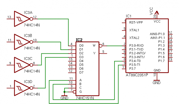
Yes this circuit looks incomplete because some parts are irrelevant. The inputs of the schmitt triggers are actually connected to raw IR sensors in an inverted fashion.
The micro selects the desired sensor via ports P3.4 and P3.5.
When the sensor with the light detected is selected, then logic low is sent to RXD of the microcontroller. Otherwise, logic high is sent. This complies with the RS-232 standard that data doesn't start until logic low is received.
I have ran tests on this circuit and the tests passed, but now I need to make things happen in a timely manner. I also did not show it, but I do have output (LAZER) connected to P3.1 (TXD) line.
My objective is to have the lazer of another unit (with the same circuitry) send a beam out when desired and have the remote unit successfully detect the lazer beam and also to detect where the beam comes from.
This is my code as an attempt to make this unit a success. Its written for the AT89C4051 with a 22Mhz crystal attached.
MAXUNITS equ 18h ;25 units
;MAGIC=bit stream for shot
MAGICS equ 00011110b
MAGIC equ MAGICS*2
OUTHW equ P3   ;output hardware
ISHOT equ P3.0 ;incoming hit
OSHOT equ P3.1 ;shoot (beam) out
SAVPSW equ 0Ch
SAVACC equ 0Dh
SENSLOC equ 08h
FOUT equ 11h   ;fire out
HITC equ 18h   ;100 unit hit counts: 4 bytes a unit. 1 byte per sensor.
;SENSLOC from address 08h to 0Bh is
;preloaded with values FFh, EFh, DFh and CFh to
;help select sensor. R0 is current sensor address.
;Timer runs every 125mS
timer0:
    mov SAVACC,A        ;Save accumulator
    mov SAVPSW,PSW      ;Save Carry
    mov C,ISHOT         ;Check current sensor
    mov A,R3            ;R3=incoming shot circular bit buffer
    rlc A               ;Add current sensor status to it
    mov R3,A            ;and update
    mov A,FOUT          ;FOUT=outgoing shot circular bit buffer
    mov C,ACC.7         ;Enable wrapping around so every 8th byte,
                        ;output repeats
    rlc A
    mov FOUT,A          ;update
    mov OSHOT,C         ;Send shot out to beam
      djnz R4,noscanend ;Repeat for 7 more bits
        cjne R3,#MAGICS,nphit ;see if incoming data is valid
          mov A,@R0           ;it is, so see which sensor its from
          swap A
          anl A,#3h           ;format it so # is 0 to 3
          mov R6,A            ;Save number to R6
          mov A,R2            ;find out current unit number 1-24
          dec A               ;subtract 1
          rl A                ;multiply by 4
          rl A
          add A,#HITC   ;Add to counter address
          add A,R6      ;Add sensor #
          xch A,R1      ;swap A with R1
          inc @R1       ;increment # times that unit hit sensor @R0
          xch A,R1      ;swap back. R1 is not wrecked.
        nphit:
        inc R0                 ;Try next sensor
        cjne R0,#SENSLOC+4,nss ;See if we are at end
          mov FOUT,#0FFh       ;We are, so turn output beam off
          setb FIRED
          mov R0,#SENSLOC      ;Go to beginning
          djnz R2,nominp       ;Go to next unit number
          mov R2,#MAXUNITS     ;If unit 0 then go to maximum unit number
          nominp:
          mov A,R2
          cjne A,ME,nss         ;See if unit is this one
            jnb WANTFIRE,nss    ;It is so see if we want to start a shot
               clr WANTFIRE     ;We do so clear request
               mov FOUT,#MAGIC  ;and set output beam to magic number
        nss:
        mov OUTHW,@R0   ;Literally select next sensor in hardware
        mov R3,#0FFh    ;Set input sensor to 1's in case we get nothing
        mov R4,#8h      ;set bit count to 8 again
    noscanend:
    mov A,SAVACC        ;restore Accumulator
    mov PSW,SAVPSW      ;restore PSW
reti                    ;exit interrupt
So I ran this code through a simulator manually putting in values for the RXD line and trying to line everything up but it seems as if the reception is always one bit behind. Maybe there is a book on serial port magic that I'm missing but I don't know.
So anyways, after running it, The transmit value is always correct and after every 8th bit, it goes to 3Ch again until 32 bits have been transmitted (8 bits for each sensor) then it goes to 0FFh which is correct.
I manually copy its value to load into RXD (I'm effectively pretending that I have a loopback cable connected between RXD and TXD here)
But after 8 iterations, As I said, transmit value is correct (of 3Ch), but the receive value isn't quite right. I was expecting 1Eh, but instead I got 9Eh. I figure 1Eh would work because 3Ch is 00111100b and 1Eh = 00011110b which is one shifted over.
Is there something I can do to fix the alignment here so that I get the same magic number everytime a valid shot is detected on any sensor regardless of what unit hit it? I mean I don't mind changing the number, but using something like 0h or FFh would be me asking to take a continuous on flashlight or extreme darkness as a valid shot but I don't want that.
Any ideas?
quote : "I was expecting 1Eh, but instead I got 9Eh."
I didn't check your code but, by the above statement, I'd check the configuration of the serial port, especially number of bits and parity.
Hi,
I guess the problem lies within the start bit. If you use the UART feature (do you? 8051 assembly is not my speciality), the first bit is discarded since it is the start bit.
You'd need to present the RxD pin with a low level for one bit time and then start the loop.
Regards,
Christian
I'm not using the internal UART.
Every 8 loops, just reset the value. Remember KISS .....


