


Introduction to Microcontrollers - Hello World
Quick Links
- Part 1: Introduction to Microcontrollers - Beginnings
- Part 2: Introduction to Microcontrollers - Further Beginnings
- Part 3: Introduction to Microcontrollers - Hello World
- Part 4: Introduction to Microcontrollers - More On GPIO
- Part 5: Introduction to Microcontrollers - Interrupts
- Part 6: Introduction to Microcontrollers - More On Interrupts
- Part 7: Introduction to Microcontrollers - Timers
- Part 8: Introduction to Microcontrollers - Adding Some Real-World Hardware
- Part 9: Introduction to Microcontrollers - More Timers and Displays
- Part 10: Introduction to Microcontrollers - Buttons and Bouncing
- Part 11: Introduction to Microcontrollers - Button Matrix & Auto Repeating
- Part 12: Introduction to Microcontrollers - Driving WS2812 RGB LEDs
- Part 13: Introduction to Microcontrollers - 7-segment displays & Multiplexing
- Part 14: Introduction to Microcontrollers - Ada - 7 Segments and Catching Errors
Embedded Hello World
A standard first program on an embedded platform is the blinking LED. Getting an LED to blink demonstrates that you have your toolchain set up correctly, that you are able to download your program code into the μC, and that the μC and associated circuitry (e.g. the power supply) is all working. It can even give you good evidence as to the clock rate that your microcontroller is running (something that trips up a great many people, believe it or not).
A program to blink an LED must do the following things:
• Set a GPIO (general purpose input/output) pin to be an output
• Drive this output pin (connected to an LED) alternately high (1) and low (0)
• Delay a human-discernable length of time between each output pin change
Our Target Hardware
As mentioned in an earlier tutorial chapter, this tutorial will focus on two microcontroller families: the AVR, using (at least in the beginning) the ATmega8515 which comes included with the STK-500, and the ARM Cortex M3, using the STM32F100RB device found on the STM32VLDiscovery board. For conciseness, in the future any AVR part will just be referred to as the AVR, and the STM32F100RB will be referred to as the STM32.
Here are links to the relevant datasheets and reference manuals:
STM32F1 Family Reference Manual
Configuring GPIO pins
GPIO pins are normally configured on reset as inputs, but they can be reconfigured under program control. GPIO pin options can vary from a few simple choices (input or output) to a fairly complex set of choices. The AVR family is on the simple side of the spectrum. An AVR GPIO pin can be configured as an input or as an output. Additionally, if a pin is configured as an input, it can further be configured to enable a weak internal pullup resistor on the input. So the three choices are ouput, input, or input with internal pullup.
For the STM32, there are many more options, including both internal pullups and internal pulldowns, as well as various output configurations, and speed ratings to offer tradeoffs between output switching speed and EMI (electromagnetic interference). In addition, before using an STM32 GPIO port, that port's clock must be enabled.
It is worth noting here that the AVR ports are 8 bits wide, while the STM32 ports are 12 bits wide.
Bit Manipulation
Embedded programs will typically do a fair amount of bit manipulation, both input and output. All kinds of switches, sensors, drivers, actuators, and other input and output devices are represented in the program as individual bits or collections of bits. Not only that, but a μC will have many configuration and status registers which will call for the setting or clearing of individual configuration bits, and the reading of individual status bits.
In our first example programs we will see LEDs and switches represented as individual bits, and later many other input and output devices will be added to that list. Thus it is important to understand how to manipulate bits, that is, to read individual bit states and to set or clear individual bit states.
What makes bit manipulation non-trivial is that bits do not usually exist alone, but exist within bytes (and 16-bit words and 32-bit words). Thus it becomes necessary, when writing individual bits, to avoid changing other bits within the same byte/word, and when reading individual bits, to avoid reading (or ignore) other bits within the same byte/word. The CPU logic instructions, as discussed in an earlier section, are what allow us to do these things.
It must be noted that some μC families also include instructions that directly act on individual bits, at least individual bits in certain registers or address ranges. These instructions are commonly used for reading and writing bits in configuration and status registers, and for maintaining bit flags in memory. These instructions, while nice to have, are not a necessity, and the standard logic instructions can always do the same job (with one or two caveats that we will discuss in the future). What's more, standard C and other high-level languages will not have language constructs designed to access individual bits, even if the μC does have individual bit instructions. If you are writing in a high-level language, it will be up to your compiler as to whether it recognizes individual bit manipulations and uses specialized instructions in those cases.
It should also be pointed out that while C is good at manipulating bits, it it not as good as assembly language. That is to say, there are some bit manipulations that can only be done awkwardly, if at all, in C, that can be done easily in ASM. Which manipulations fall into this category will depend on the particular instruction set of the μC in question. A couple of general examples are, shifting or rotating data through arbitrary numbers of bytes, and using the value of the carry flag, sign flag or other condition flags directly as data bits. As I said, there may be others as well, depending on the underlying instruction set.
Data Sizes
Before we start talking about time delays, this is probably as good a place as any to examine and emphasize the range of values that can be represented by data variables of different byte sizes. These are numbers that μC programmers will deal with throughout their careers, so get to know them well:
• 1 byte (8 bits):    0 to 255 unsigned             -128 to 127 signed
• 2 bytes (16 bits):  0 to 65,535 unsigned          -32,768 to 32,767 signed
• 4 bytes (32 bits):  0 to 4,294,967,295 unsigned   -2,147,483,678 to 2,147,483,677 signed
(for 32 bits I just think 0 to 4 billion unsigned, -2 billion to +2 billion signed)
Simple Time Delays
While there are many ways to execute time delays and generate time intervals, the simplest (but not the best) is a software delay. This just involves sitting in a do-nothing loop for the desired length of time, and then exiting the loop. Since microcontrollers are so fast, a one-second delay may loop hundreds of thousands or millions of times. These are hundreds of thousands or millions of CPU clock cycles that are being wasted, not available for doing any other useful work. For this reason, software delays are not generally a good idea, even though they are easy to understand for beginners.
For a suitable LED blink rate, a useful rule of thumb for estimating how many times a software delay should loop is to divide the μC clock rate by 100. Use this count for both the LED ON and OFF times, so the total LED delay for one blink cycle is twice this value. Thus an AVR running at 1MHz would delay loop 10,000 times while ON, then 10,000 times while OFF, and the STM32 running at 8MHz would delay loop 80,000 times ON and the same number OFF. This is just a rule of thumb, of course, and the numbers can be increased or decreased, but it's a really easy number to calculate, and it generally gives a number that results in a good blink rate. A good blink rate is simply one where the total blink period is not so small that the LED blinks too fast to notice it is blinking (say 20 or more times per second), nor so large that the LED takes many seconds to blink, forcing you to sit and stare at it to see if your program is working at all.
At Last, It Blinks! (AVR version)
It's taken a while to lay the groundwork, but we're finally ready to blink our danged LED. We will write our LED blinky program in C, and follow up with ASM versions in a future tutorial chapter.
For the AVR, the C LED blinky program is dead simple, largely because the total AVR initialization is one line of code. For the STM the actual blinky code is identical, but the configuration is a bit more complex. Both the STK-500 and the STM32VLDiscovery boards have built-in LEDs, but if you're using some other hardware that doesn't have any built-in LEDs you'll need to wire one in. We will talk more about this in a future chapter, but for now you can just connect your chosen GPIO pin to a resistor of around 470 - 1000 Ohms, connect the other end of the resistor to the anode of the LED, and connect the cathode of the LED to ground (GND). For future reference, this makes your LED "active high." To test your LED wiring, disconnect power to the board, remove the resistor lead from the GPIO pin and connect it to Vcc or Vdd (the same voltage that powers your microcontroller), then apply power. The LED should light up. Once you've confirmed your LED wiring is good, disconnect power, remove the resistor lead from Vcc/Vdd and reconnect the lead back to the GPIO pin. Under no circumstances have the GPIO pin connected directly to Vcc/Vdd!
Here is a drawing of an LED wired active high (A), and one wired active low (B)
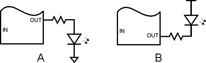
So here is our AVR Embedded Hello World blinky program, step by step.
Step 1 - Create Empty Program
Atmel Studio will create an empty program for you, including all the chip-specific data for the microcontroller you specify. If you are using a different compiler, or even a different language, the documentation for the compiler will tell you how to create an empty program.
Step 2 - Add AVR Initialization
Initializing the AVR involves two components: setting up the AVR clock, and configuring the selected GPIO pin as an output. The first of these, setting up the clock, does not involve any program code, but is done by configuring the AVR fuses. For simplicity we will use the AVR clock settings as it comes from the factory. These settings select the internal 8 MHz RC clock, and select a clock divider of 8, resulting in the chip running off the internal clock at a speed of 1 MHz.
Configuring the LED GPIO pin as an output is simplicity itself. Simply write a 1 into the proper bit position of the chosen port. Let's pick bit 0 of port B as our LED pin. Setting this pin as an output takes the following line of code:
DDRB = (1<<0);
This sets the pin corresponding to PORT B bit 0 to an output, and all other PORT B pins to inputs. Or, to leave the other bits of DDRB unchanged (they may have already been set earlier in the program)
DDRB |= (1<<0);
Step 3 - Add a Software Delay Function
The software delay function will take an input value and count that value down to 0, then return. The larger the value the longer it will take to count down to 0, hence the longer the delay.
Depending on the range of input values needed, the input value will either be declared as a 16-bit or a 32-bit variable. As mentioned earlier, on an 8 bit device like the AVR, decrementing a 32-bit variable will take longer than decrementing a 16-bit variable, but this is not really an issue since it can be accounted for by using a smaller delay value.
Using our blink count rule of thumb, our blink delay will take 1,000,000/100 = 10,000 cycle loops (1,000,000 is our AVR clock rate). Remembering our data size vs numeric range table, 10,000 can fit into a 16 bit variable, but later we will speed up our AVR to 8 MHz (and other AVRs can run up to 20 MHz), so we'll use a 32-bit variable to be able to accomodate those higher clock rates. So here is our delay function:
void delay(volatile uint32_t d)
{
  while (d-- != 0)
    ;
}
The declaration of the delay count 'd' sets it to a 32-bit unsigned variable (uint32_t), and also uses the 'volatile' keyword to prevent the compiler from possibly optimizing away the "useless" function (the function doesn't change anything in the program and is therefore unnecessary, in the view of the compiler). Without 'volatile' the entire delay function might get optimized into nothing and your LED would end up blinking hundreds of thousands of times a second.
Step 4 - Write the LED Blink Loop
The obvious way to write the blink loop would seem to be this:
- Turn LED ON
- Delay
- Turn LED OFF
- Delay
- Loop Back
But there's another way that eliminates almost half of the loop code:
- XOR LED bit
- Delay
- Loop Back
The penalty for this method is that the LED ON and OFF times will always be the same, while with the first method one could use different values for the ON and OFF delays. As usual, there's a tradeoff. For our LED blinky we'll use this second method.
Step 5 - Download Program to Your Hardware
This step is very dependent on the tools you are using, both the language toolchain (in my case, Atmel Studio) and the programming hardware (in my case, the STK-500). Once you have the programming hardware connected, you will tell your toolchain the name and location of the file you are downloading, and download it. The program should then start to run on your hardware. The file you download will be the output of your toolchain. It may be a .hex file, a .elf file, or some other file. You will have to determine what types of files your toolchain can generate, and what types your programming hardware can work with. For the Atmel Studio / STK-500 setup a .hex file is used.
Now we have all the parts we need for our AVR LED blinky program. Here it is - it has been run on the STK-500 board and blinks 2/sec using the default compiler optimization of Os. Note that if you are using the STK-500 you will have to set up your STK-500 board to connect PORTB to the LEDs, using one of the supplied 10 conductor ribbon cables. You will also have to connect the ISP connector to the correct connector for the ATmega8515 using the 6 conductor ribbon cable. All of this is in the STK-500 documentation.
If you run your program and your LED just lights up, this can mean a few different things. Your delay loop may be running much slower than you think (resulting in a very long ON time that looks like the LED is just stuck ON), or may be running much faster than you think (resulting in an LED blinking so fast it just looks like it's ON). A quick check for either condition is to try your program with a delay 10 times shorter than you calculated, and a delay 10 times longer than you calculated. This may bring the blink rate into the visible range. If you have a scope, just put it on the LED and you'll see if it's blinking too fast, but the scope can't tell you it's blinking too slow any better than your eyes can tell you. Other reasons your LED may just light up (or stay dark) are that you've wired the LED to a different port pin than you are toggling in the program, or that you've compiled for the wrong chip, or that you had a compiler or build error that you didn't notice, or that your download mechanism isn't working, or that your download cable or connector is bad or wired wrong, or that your hardware is dead (Do you have Vcc to all power pins, and GND to all ground pins?).
Enough of that. Here is the AVR LED Blinky "Hello World":
// AVR_BL1
// Blink LED on PB0
// Clock fuses set for 1 MHz internal clock

#include <avr/io.h>
#include <stdint.h>

void delay(volatile uint32_t d)
{
  while (d-- != 0)     // loops while non-0 and decrements
    ;
}

int main(void)
{
  DDRB = (1<<PB0);     // PB0 (=0) is our LED output bit; (1<<PB0) = 1

  while(1)             // forever loop
  {
    PORTB ^= (1<<PB0); // toggle LED bit
    delay(10000);      // 1 MHz / 100
  }
}
At Last, It Blinks! (STM32 version)
As mentioned above, the actual blink loop for the STM32 is identical in operation to that for the AVR. The main difference in programs is that the STM32 requires more configuration to get up and running, and of course all the chip registers are different as is their configuration. The other difference relates to clock rates. The AVR is running on its internal oscillator at its out-of-the-box rate of 1 MHz (though the chip is capable of running at 16 MHz, and some AVRs can run at 20 MHz). The STM32 can run at a clock rate of 24 MHz, but runs out of the box at 8 MHz using an internal oscillator. So our delay loop count will be 8,000,000/100 or 80,000. Thats it, all the differences between the two programs.
No special connection or configuration is required for the STM32VLDiscovery board. Just connect it to your PC USB port. The programming interface will be ST Link, which should be an option in your toolchain.
Here is the STM32 version of the program. It blinks at about 4.5/sec using the "None" optimizer setting.
// STM32_BL1
// Blink LED on PC9
// Default 8 MHz internal clock

#include <stm32f10x.h>

void delay(volatile uint32_t d)
{
  while (d-- != 0)
    ;
}

int main(void)
{
  RCC->APB2ENR = RCC_APB2ENR_IOPCEN;  // enable PORTC
  GPIOC->CRH = (0b0010 << 4);  // CNF=0, MODE=2 (2MHz output)

  while (1)                    // forever loop
  {
    GPIOC->ODR ^= (1<<9);      // toggle green LED
    delay(80000);
  }
}
By the way, when testing this code I had forgotten to add 'volatile' to the declaration of the delay parameter, and the LED just lit up and stayed lit. I put the scope on the LED pin and saw that the LED was actually blinking every few microseconds, and immediately knew what I had done wrong (without 'volatile' the optimization setting I was testing had optimized away the entire delay routine, exactly as mentioned above). Without a scope that would have been a much harder problem to solve, since the 10x faster and 10x slower fixes would not have made any difference. I wasn't kidding when I said you really should try to get a scope if at all possible. I can't tell you how many times I've seen a beginner write about how some problem has cost him days or weeks, when a scope would have found the problem in minutes.


- Comments
- Write a Comment Select to add a comment
I'm sorry, but apparently my comment did not post fully. On your line
DDRB=(1"left shift"PB0);
what is the purpose of the bit shift operator. If we need to write a one to the address, why could you not simply write
DDRB=1; ?
Moreover, does this line make use of the fact that PB0 defaults to zero? If PB0 defaulted to one, that would be equivalent to DDRB=(1"left shift"1)=2. In other words, you would be writing a one to the second bit instead of the first.
I know that I'm missing something very basic here, and I apologize for the total noob question. Thanks in advance!

As a general rule, never code with magic numbers such as 1 if you can avoid it. Derive them in the code from named constants.
your tutorial is very informative and is turning out to be of great help in clearing a lot of my concepts.
I however need some help from you. I am using SK-PM9G45 starter kit. This controller is similar to AT91SAM9G45 and is an ARM9 controller. I would need your help in enabling the PIO pins for the led blinking program. I am posting links of the data sheet that might give you further insight into the controller.
Hoping to hear from you soon.
Links:-
1) http://download.ronetix.info/boards/doc/PM9G45/SK-PM9G45-datasheet.pdf
2) http://download.ronetix.info/boards/doc/PM9G45/PM9G45-DataSheet.pdf.
Thank you & regards.
I'm JUST starting to learn about microcontrollers and embedded software. Your tutorial is literally the first thing I found on google. I have some very basic questions about your code. I understand the "<<" operator to mean a left shift of the BYTE. On your line
DDRB=(1<
DDRB=(1<
check againg, regards
I'm using a STM32F105RC and keil uVision software. Somehow, when I copied the code you provided, at compilation I've got this error:
main.c(25): error: #18: expected a ")"
GPIOC->CRH = (0b0010 << 4); // CNF=0, MODE=2 (2MHz output)
Any idea where it might come from?
Thanks in advance!!
I would love to know why but, honestly I have no freakin' idea. If any of you know, please leave a reply
:D
Hi,
I am trying to learn NIOS II processor programming. The thing is, I don't have any embedded development experience. But yes I know C/C++, and have developed few systems on FPGAs using Verilog (Xilinx Virtex).
So where to start from? any road map?
Whenever I start programming it, macros and processor jargon really confuses me. Even the C which is given in the software developers guide is bit confusing..
Please suggest.
How come the AVR LED blinks 2/sec, since the delay is a 100th of the clock speed? Shouldn't it blink at 100/sec? Is it because in actuality, there are about 50 CPU instructions that need to be carried out on each loop iteration?
Hi,
Nice tutorial!!
Please share some knowledge on developing device driver development.
Thanks
Regards
Vishal
To post reply to a comment, click on the 'reply' button attached to each comment. To post a new comment (not a reply to a comment) check out the 'Write a Comment' tab at the top of the comments.
Please login (on the right) if you already have an account on this platform.
Otherwise, please use this form to register (free) an join one of the largest online community for Electrical/Embedded/DSP/FPGA/ML engineers:


