


Introduction to Microcontrollers - More On GPIO
Now that we have our LED Blinky program nailed down, it's time to look more closely at outputs, add button/switch inputs, and work with reading inputs and driving outputs based on those inputs.
Quick Links
- Part 1: Introduction to Microcontrollers - Beginnings
- Part 2: Introduction to Microcontrollers - Further Beginnings
- Part 3: Introduction to Microcontrollers - Hello World
- Part 4: Introduction to Microcontrollers - More On GPIO
- Part 5: Introduction to Microcontrollers - Interrupts
- Part 6: Introduction to Microcontrollers - More On Interrupts
- Part 7: Introduction to Microcontrollers - Timers
- Part 8: Introduction to Microcontrollers - Adding Some Real-World Hardware
- Part 9: Introduction to Microcontrollers - More Timers and Displays
- Part 10: Introduction to Microcontrollers - Buttons and Bouncing
- Part 11: Introduction to Microcontrollers - Button Matrix & Auto Repeating
- Part 12: Introduction to Microcontrollers - Driving WS2812 RGB LEDs
- Part 13: Introduction to Microcontrollers - 7-segment displays & Multiplexing
- Part 14: Introduction to Microcontrollers - Ada - 7 Segments and Catching Errors
It's ON - No, It's OFF - No, It's ON...
I have to confess, I cheated. Well, let's say I glossed over something very important. In our LED Blinky program, we never cared about whether an output '1' or an output '0' turned on the LED. Since we were just flashing with a 50/50 duty cycle, it was enough to simply alternate between 1 and 0. But that is one of the very, very few cases where you won't need to know your output polarities.
Basically, to turn on an LED we need to drive current through it, which means putting a voltage differential across it. That differential is not fixed but varies with LED color and current, but it's about 2V at the low end and 3.5V at the high end. We add a series resistor to drop the remaining voltage at our chosen LED current (e.g. with a 2V LED and a 5V Vcc we need to drop that extra 3V). Since microcontroller outputs drive near 0V (GND) for a '0' and near Vcc for a '1', you can either turn on an LED with a '1' by connecting the other end of the LED/resistor combination to GND, or turn it on with a '0' by connecting the other end to Vcc - the LED doesn't care at all.
There are general terms that describe whether a '1' or a '0' turns on the circuitry connected to an output. Circuitry turned on by a '1' is called "active high," and circuitry turned on by a '0' is called "active low." As it happens, the LEDs on the STK-500 are active low, and on the STM32VLDiscovery they are active high. Even though the two boards have opposite polarity active LED outputs, the same simple blink code works with both of them, as discussed above. A quick way to see the effect of LED output polarity is to make the ON delay much different (either shorter or longer) than the OFF delay. A difference of 10 to 1 will be clearly visible (though you may need to increase both of your delays to slow down the blink enough for the difference to be apparent, while keeping the 10 to 1 ratio). A 10 to 1 ratio also has the advantage that you can change your long delay to a short delay by deleting a 0, and your short delay to a long delay by adding a 0. Now it is no longer enough to simply XOR the LED output bit, since we have two different delays. So our LED Blinky program now looks like this (AVR shown, STM32 identical in operation, exercise left to the reader):
// AVR_BL2
// Blink LED on PB0, 1/10
// Clock fuses set for 1 MHz internal clock

#include <avr/io.h>
#include <stdint.h>

void delay(volatile uint32_t d)
{
  while (d-- != 0)      // loops while non-0 and decrements
    ;
}

int main(void)
{
  DDRB = (1<<PB0);      // PB0 (=0) is LED output bit; (1<<PB0) = 1

  while(1)
  {
    PORTB |= (1<<PB0);  // set LED bit (LED ON for active high, OFF for active low)
    delay(2000);        // short delay
    PORTB &= ~(1<<PB0); // clear LED bit (LED OFF for active high, ON for active low)
    delay(20000);       // long delay
  }
}
So now we are first using the OR operator |= to set the output bit for a short time, then the AND operator to clear the output bit for a 10x longer time. For the STK-500 with active low LEDs this will result in a short LED OFF and a longer LED ON. For the STM32VLDiscovery the same code would produce a short LED ON and a longer LED OFF. By running the program twice, once with the long delay after the |= followed by the short delay, and once with the short delay after the |= followed by the long delay, you can confirm (or determine) whether your particular LED setup is active high or active low.
What Happens If I Push This Button?
Well, not a lot until you program it. A button (or switch or key, they're all switches, and everything that follows applies to buttons, switches and keys) will be wired so as to drive an input pin, which is sitting at a certain state, to the opposite state when pushed or activated. Most commonly, a button will be wired so that the input is held high ('1') when not pushed, and brings the input low ('0') when pushed. This is how you should wire your buttons in most cases, but it is also possible to wire a button so that the input is held low ('0') when not pushed, and brings the input high ('1') when pushed. In either case, your software will look for the input state to go from the inactive state to the active state, indicating a button (/switch/key) push.
The concept of active high and active low, discussed above for outputs, also applies to inputs. If your button is wired so that it goes to '0' when pushed, it is an active low button. If wired so that it goes to '1' when pushed, it is active high. You will have to account for the polarity of your button inputs in your button reading software, but this is quite simple. Note that there is nothing to prevent you from having some active high buttons and some active low buttons, even on the same input port. This also applies to having inputs and outputs on the same port - it's not a problem, and is in fact extremely common. And to answer the next question, yes, you can have active high outputs, active low outputs, active high inputs and active low inputs, all on the same port.
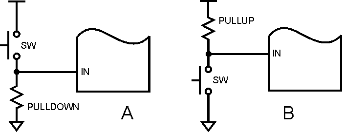
Here is a diagram of a button wired active high (A) and one wired active low (B). The resistor holds the input in the inactive state until the button is closed, at which point the input is pulled to the active state. If you want you can think of it as a resistive divider, with the switch being a billion Ohms when open, and 0 Ohms when closed. A typical pullup or pulldown resistor, which might be built into the uC or might be an external component, would be in the range of 10 to 100 kOhms.
One Bit, Just One
Just like outputs, inputs come in bunches. AVR inputs (and outputs) come in ports of 8 bits. STM32 inputs and outputs come in ports of 12 bits. We glossed over this when we were blinking our LED, but it's time to talk in more detail about isolating one bit out of a port, both in input and in output modes. And keep in mind that everything that applies to a single bit can also apply to multiple input and output bits.
As we saw with our LED blinky code, we can isolate a single output bit in a port using the bitwise OR operators (| or |=) and the bitwise AND operators (& or &=). These operators will map to corresponding CPU OR and AND instructions. To set a single bit, you OR a 1 into that bit position, and 0s in all the other bit positions. Likewise, to clear a single bit, you AND a 0 into that bit position, and 1s in all the other bit positions. These operations force a 1 or 0 into the selected bit position, while leaving all the other bit positions unchanged.
To isolate a single input bit, we use the AND operator to read that bit position while putting 0s into all the other read bit positions. This gives us an N-bit word with one bit holding the value of the desired input bit, and all the other bits holding 0s. That means the entire word will be 0 if the desired input bit was '0', or the entire word will be some non-zero value if the desired input bit was '1'. It is important to understand that the result will not, in general, be a word that contains a 0 or a 1, but a word that contains a 0 or some non-zero value. Thus you will not, in general, test the word for 0 or 1, but for 0 or non-zero. For example, if the desired input bit is bit 5, the word will either be 0 or 1<<5, that is, either 0 or 32. It is a common mistake to test for a 1 in such cases instead of testing for non-zero.
And to reiterate, all of this applies to multiple bits as well as to single bits. Thus you could set bits 1, 3 and 4, and clear bits 0 and 5, as follows:
PORTA |= 0b00011010
PORTA &= 0b11011110
In a future chapter we will discuss possible problems with the above, and ways to solve those problems.
Note that in the 2nd code line above we have 0s in bits 0 and 5, and 1s in all the other bits. This is the correct way to clear bits 0 and 5, but in many cases you want to indicate the bits in a more symbolic way such as
PORTA &= ((1<<5) | (1<<0)); // right side is 0b00100001
Now we're being explicit about the bits we want to operate on, but the polarity is wrong! We've got 0s where we want 1s, and 1s where we want 0s. So we'll use the very handy C bitwise inversion operator '~', which may translate to a CPU instruction called NOT or COM (for complement):
PORTA &= ~((1<<5) | (1<<0)); // right side is 0b11011110
You can also check for multiple inputs, such as bits 0, 1 and 2, as follows:
inputs = PORTB & 0b00000111;
Since in many cases your buttons will be wired active low, this puts 0s in all your unwanted bits, and also puts 0s in your active button bits - the ones being pushed. That's clumsy, since we have 0 representing both "ignore" and "active". The solution is once again to use bitwise inversion, this time on the raw input before doing the masking:
inputs = ~PORTB & 0b00000111;
Now when we do the mask, our active button bits will be '1', and both our inactive button bits and our "ignore" bits will be '0', which is a much more consistent representation.
Using a Button to Control an LED
The simplest way to have a button control an LED is to turn the LED ON when the button is depressed (active), and turn it OFF when the button is released. There are other behaviors we could also program, such as push ON / push OFF, but we will leave those for later exploration.
Our simple button/LED program consists of a loop that continuously reads the button input and sets the LED output accordingly. Such a loop will execute hundreds of thousands of times a second - far, far faster than it needs to execute to control an LED with a response acceptable to a human. It would be perfectly fine to only check the button and control the LED every 10 to 25ms (the human response interval we will discuss in the next section), but that takes more work because we have to add a delay, and a delay serves no purpose here. Later we will learn how to perform useful work during those delays, and then it will make sense to check human inputs and produce human outputs at the rate of 10s per second, not hundreds of thousands per second. But for now we'll just run the loop at full speed since that produces the simplest code.
To control our LED with a button, we will take our LED blinking program and change the code inside the infinte (or forever) loop. Each time through our loop we will check the button and, depending on whether the button is pushed or released - active or inactive - we will turn the LED ON or OFF.
Here is the AVR version of LED control program. Note that we don't configure our input bit, PA7, as an input. This is because when the AVR comes out of RESET, all of the GPIO pins are automatically configured as inputs. Input is the default GPIO state.
// AVR_CL1
// Control LED on PB0 using button on PA7
// Clock fuses set for 1 MHz internal clock

#include <avr/io.h>
#include <stdint.h>

int main(void)
{
  DDRB = 1<<PB0;          // PB0 is output, all others input

  while(1)
  {
    if (PINA & (1<<PA7))  // test PA7 for 0 or non-0
    {
      PORTB |= (1<<PB0);  // clr LED
    }
    else
    {
      PORTB &= ~(1<<PB0); // set LED
    }
  }
}
And here is the STM32 version. Once again, we do not have to configure PA0 as an input because all GPIO pins are configured as inputs when the μC comes out of RESET.
// STM32_CL1
// Control LED on PC9 with button on PA0
// Default 8 MHz internal clock

#include <stm32f10x.h>

int main(void)
{
  RCC->APB2ENR |= RCC_APB2ENR_IOPCEN; // enable PORTC for LED output
  GPIOC->CRH = (0b0010 << 4);         // CNF=0, MODE=2 (2MHz output)

  while (1)
  {
    if (GPIOA->IDR & (1<<0)
    {
      GPIOC->ODR |= (1<<9);        // set green LED
    }
    else
    {
      GPIOC->ODR &= ~(1<<9);       // clr green LED
    }
  }
}
Both of these programs behave identically. Push the button and the LED goes ON. Release the button and the LED goes OFF. But wait, the AVR LED is active low, and the STM32 LED is active high - how can they both behave the same way? The answer is that the STK-500 button inputs are wired active low, and the STM32VLDiscovery buttons are wired active high. For both boards, the polarity of the input buttons and the output LEDs is the same. For the AVR board both are active low, and for the STM32 board both are active high. This is why both programs behave the same. A '0' on the input pin produces a '0' on the output pin, and a '1' produces a '1'. If you had a board where the polarity of the inputs was opposite to the polarity of the outputs (a perfectly reasonable possibility), you would have to reverse the logic in the if-else statement, or else the LED would be ON when the button is not pushed, and would go OFF when the button is pushed.
The point of this is to always know the polarity of the signals you are dealing with, both inputs and outputs.
The User Can Push a Button At Any Time (the Rat)
Inputs are fundamentally different than outputs in that outputs are under your program's control - they happen when your program chooses for them to happen - while inputs can happen whenever and wherever. To avoid missing any inputs, your program has to act as if it is always watching the inputs, even while it is doing all the other stuff it needs to do. Depending on the number and speed of the inputs, and on what that "other stuff" is, this can be fairly simple or it can get rather complicated, but it must be done if your program is to be reliable.
In the case of buttons, the key (!) questions to ask are "how quickly can a user press and release a button?" and "how soon after the user presses a button does my program have to act?" The first question is about making sure your program doesn't completely miss a user button push. The second question is about making sure your program is properly responsive, not "slow" or "lagging" or "really annoying!"
To provide some numbers, a typical real-life button push might be as short as 50-100 milliseconds (I just timed a bunch at 60-100ms). A good response time might be 100ms. What this means is that you have to be checking your buttons at least every 50ms to make sure you don't miss any, and to have suitable response time. I would consider a checking interval of between 10 and 25ms much better. This means that whatever else your program is doing it needs to come back and check for button pushes 40 to 100 times per second. Luckily this is not as hard as it might sound, but it does require a bit of cleverness, as we will see in a future chapter.
But I Only Pressed It Once!
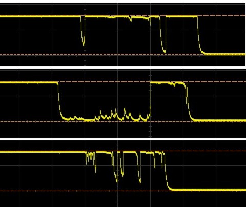
As if needing to be sure to read buttons faster than a human can press them was not enough of an issue, it turns out that you also need to be sure not to read buttons TOO fast. The reason for that is that most buttons and other mechanical contacts "bounce." This means that when they open or close, the mechanical bits inside twist and bounce and vibrate and they can actually produce multiple make or break signals for a single real make or break. Over a period of a few hundred microseconds, a button may open and close 2 to 20 times or more, resulting in 2 to 20 or more button "events." Remembering that we have microcontrollers that can execute 10 to 100 or more instructions in a microsecond, it would be a trivial matter for a μC to sense each of those 2-20 button events. Is this a problem? Well, imagine if you sent somebody money via Paypal and you ended up sending the same amount 14 separate times because your ENTER key bounced.
Here are 3 scope pictures of the same button pushed 3 different times. The timescale is 100us / division. See the problem now?
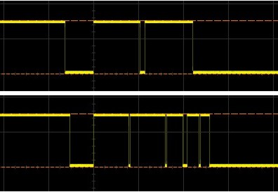
But wait! you object. The Control LED program above works and it is reading the button extremely often, tens or hundreds of times per millisecond. That is correct. In this one case, it doesn't matter, because if the LED turns on and off a few times in less than a millisecond on button push or release, it doesn't matter. The phantom on and off LED pulses happen far too fast for you to notice them. But they DO happen, as can be seen by the scope images below. This shows the signal to the LED, not the input signal at the switch. So you can see that the Control LED program loop is plenty fast enough to detect the bouncing of the button and process it as multiple events. It's just that having multiple LED events doesn't matter (once again we got lucky, just as in the case of the LED polarity for 50/50 blinking). But this is generally not the case - most of the time a single button push must only register as one button event, and the code must be written so as to ignore any button bouncing. We will discuss ways to ignore bouncing, or "debounce" an input, in a future chapter when we have laid the necessary groundwork.
Here are some switch bounces that have been read by the μC and sent to the output. Same 100us / division timescale. This is exactly what you DON'T want, in most cases:
So by now you should be convinced that reading lowly buttons is a bit more involved than it would seem. In a future chapter of this tutorial we will talk about how to read buttons reliably, neither missing any real changes nor responding to any phantom changes, but before that we need to discover the wonderful world of timers, and before that we need to discover the equally wonderful world of interrupts. Good stuff coming up!


- Comments
- Write a Comment Select to add a comment
I am learning your tutorials these days to know more about microcontroller programming. Until now I have developed only applications on the processor.Never gone deep into the details as you have covered in tutorials.Can you please include on how to select which pin,which port on STM,how to understand datasheet and use for coding as mentioned in the above tutorial?
Please do what he sais!

When you look at A, you see that when SW is not active circuit is closed with the high state through resistor that pulls IN state to HIGH level, thus it should be called pull-up resistor. When you make SW active it overwrites the resistor and pulls IN to LOW state thus switch should be called active-low. But you state that A is active-high switch / pull-down resistor. I think you should switch the triangle(VCC) and line(GND) in those pictures.
Could you explain or correct me if I'm wrong, please?
To post reply to a comment, click on the 'reply' button attached to each comment. To post a new comment (not a reply to a comment) check out the 'Write a Comment' tab at the top of the comments.
Please login (on the right) if you already have an account on this platform.
Otherwise, please use this form to register (free) an join one of the largest online community for Electrical/Embedded/DSP/FPGA/ML engineers:


