


Introduction to Microcontrollers - Driving WS2812 RGB LEDs
Quick Links
- Part 1: Introduction to Microcontrollers - Beginnings
- Part 2: Introduction to Microcontrollers - Further Beginnings
- Part 3: Introduction to Microcontrollers - Hello World
- Part 4: Introduction to Microcontrollers - More On GPIO
- Part 5: Introduction to Microcontrollers - Interrupts
- Part 6: Introduction to Microcontrollers - More On Interrupts
- Part 7: Introduction to Microcontrollers - Timers
- Part 8: Introduction to Microcontrollers - Adding Some Real-World Hardware
- Part 9: Introduction to Microcontrollers - More Timers and Displays
- Part 10: Introduction to Microcontrollers - Buttons and Bouncing
- Part 11: Introduction to Microcontrollers - Button Matrix & Auto Repeating
- Part 12: Introduction to Microcontrollers - Driving WS2812 RGB LEDs
- Part 13: Introduction to Microcontrollers - 7-segment displays & Multiplexing
- Part 14: Introduction to Microcontrollers - Ada - 7 Segments and Catching Errors
This tutorial chapter is a bit of a detour, but I think an interesting and useful one. It introduces a bit of assembly language programming, and demonstrates bit-banging a tight serial data protocol. And it deals with RGB LEDs, which are just very fun in their own right, especially these new parts. So I thought I'd post this to give readers time for some holiday lighting experimenting.
Back To The Future
Remember how we started this tutorial series with simple blinking LEDs? Well there is a fairly new and very cool RGB LED on the block, known as the WS2812 (the WS2812B is the latest model). This is a surface-mount RGB LED with a built-in WS2811 driver chip in the LED package - you can see it plain as day, along with the R, G and B LEDs, when you look at the chip face. BTW, RGB stands for Red, Green, Blue, if you didn't know. With combinations of RGB you can reproduce just about any color, so in a sense a controllable RGB LED is a universal LED.
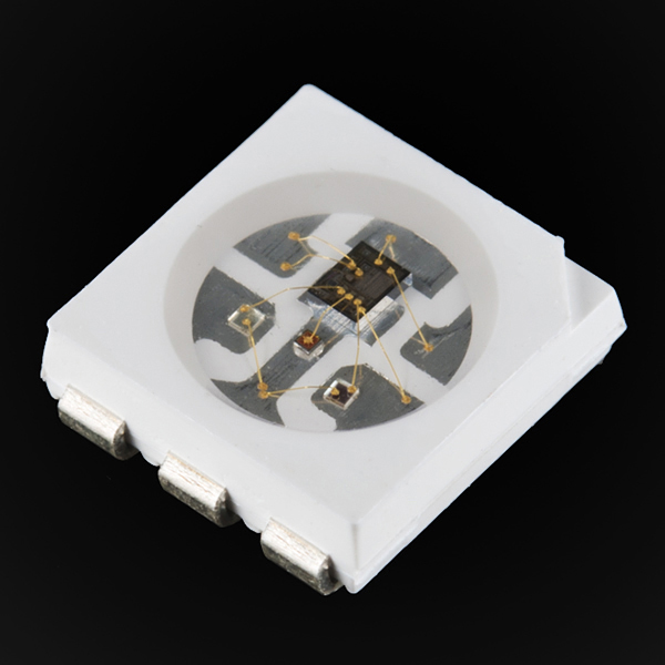
Most of the pictures I could find online show the older WS2812 part, which has a slightly different internal structure and which has 6 pins rather than the 4 pins of the WS2812B. Here is a nice picture of a WS2812 from the good folks at www.sparkfun.com. You can clearly see the 3 LED dies as well as the onboard WS2811 controller.
The WS2812B is just about the simplest device you could imagine, from a hardware standpoint. Here is a copy of the datasheet. It has 4 pins: Vdd (3.5 to 5.3VDC), GND, Din and Dout. The Din and Dout pins are where the magic happens. Data bits representing RGB brightness are fed serially into the Din pin, and the chip strips out the first 24 bits (8 bits each for R,G,B) and sends the remaining bits out the Dout pin. By connecting the LEDs in a string, with the Dout from one LED going to the Din of the next LED, each LED in turns strips off the bits it needs from the front of the data stream, and sends the rest of the data stream out to the next LED. Theoretically there's no limit to the number of LEDs you can drive with a single data line - the only limitation is that the time it takes to update all the LEDs in the string increases linearly with the number of LEDs in the string. This makes for a very clever and efficient scheme for addressing unique RGB data to any number of LEDs wired in a string.
Self-Clocking Serial Data
All serial data protocols require a clock to reassemble the received data. This clock may be an explicit clock signal such as the SCK line on an SPI device, or the clock may be an implicit, pre-agreed clock such as the baud rate settings on a UART device (with the START and STOP bits serving to synchronize the data to the pre-agreed clock), or the clock may be built into the serial data stream. The WS2812B uses a form of this 3rd method, whereby every bit consists of a '1' followed by a '0', and the bit value is determined solely by whether the '1' interval is longer or shorter than the '0' interval. For the WS2812B, each bit is defined thus:
- 0 bit: 0.40us HI, 0.85us LO
- 1 bit: 0.80us HI, 0.45us LO
Each of these timings has a tolerance of +/- 0.15us, so there is a fair amount of wiggle room given to the serial data timing. This is common with self-clocked serial data, where it is only ratios of '1' to '0' that matter, within broad timing limits.
As you can see from these numbers, a single data bit takes 1.25us. This means a single byte takes 10us, and all 3 bytes of RGB data take 30us. It is important to keep these times in mind when coming up with a way to drive the chips. Also, keep in mind that there is no delay or added time between bits or bytes or byte triplets. The only time delay that we ever add to the data stream is the 'reset' delay of at least 50us (but it can be any duration longer than that). Thus an idle '0' on the data output line of at least 50us resets all the chips for the next batch of incoming data.
Picking A Microcontroller
Between the two microcontroller families we are using in this tutorial, we will use an AVR to drive the WS2812B chips. One of the main reasons for this choice is that the WS2812B is essentially a 5V chip, and AVR can be run at 5V, unlike most ARM Cortex M3. This saves us from having to derive a 3.3V uC voltage from the 5V LED chip voltage, and from having to supply a level-shifing gate from a 3.3V uC to the 5V LED chips.
Doing The Math
Many AVRs can run on an internal oscillator of 8MHz, or 0.125us/clock. This means that a 1.25us data bit is only 10 uC clocks. That's not very many! It turns out to be possible to write AVR assembly code that can drive the WS2812B properly with an 8MHz AVR. It's a tight fit, but it can be done. We can't get the exact timing specified above, but we can get timing that fits well inside the timing limits. To be specific, we will aim for a '1' bit of 7 clocks '1' output followed by 3 clocks '0' output, and a '0' bit of 3 clocks '1' output followed by 7 clocks '0' output. Further, we need to keep to this timing over a string of N bytes (or rather, 3*N bytes for N LEDs).
I hardly ever write assembly language any more (though I read a fair amount in looking at compiler output files), so I thought this would be a fun return-to-my-roots exercise. It is also real-world evidence that using assembly language, while rare these days, is by no means dead. I can think of no way this could be done on an 8MHz AVR using C.
You will certainly need a copy of the AVR Instruction Set manual to follow this code, unless you already have it pretty much committed to memory.
The Code
What follows is the assembly language code I came up with to drive the WS2812Bs. It took a fair amount of cycle-counting and fiddling, but in the end I was pleased to discover that I hit the spec. I will list the code first, and then explain it. By the way, the function is called output_grb because for some inexplicable reason the WS2812B requires serial data in the order G-R-B rather than the universal R-G-B order. Go figure. For each byte, data is shifted out starting with the MSB, bit 7.
 #define __SFR_OFFSET 0
#include <avr/io.h>

;extern void output_grb(u8 * ptr, u16 count)
;
; r18 = data byte
; r19 = 7-bit count
; r20 = 1 output
; r21 = 0 output
; r22 = SREG save
; r24:25 = 16-bit count
; r26:27 (X) = data pointer

.equ      OUTBIT,   0


.global output_grb
output_grb:
         movw   r26, r24      ;r26:27 = X = p_buf
         movw   r24, r22      ;r24:25 = count
         in     r22, SREG     ;save SREG (global int state)
         cli                  ;no interrupts from here on, we're cycle-counting
         in     r20, PORTB
         ori    r20, (1<<OUTBIT)         ;our '1' output
         in     r21, PORTB
         andi   r21, ~(1<<OUTBIT)        ;our '0' output
         ldi    r19, 7        ;7 bit counter (8th bit is different)
         ld     r18,X+        ;get first data byte
loop1:
         out    PORTB, r20    ; 1   +0 start of a bit pulse
         lsl    r18           ; 1   +1 next bit into C, MSB first
         brcs   L1            ; 1/2 +2 branch if 1
         out    PORTB, r21    ; 1   +3 end hi for '0' bit (3 clocks hi)
         nop                  ; 1   +4
         bst    r18, 7        ; 1   +5 save last bit of data for fast branching
         subi   r19, 1        ; 1   +6 how many more bits for this byte?
         breq   bit8          ; 1/2 +7 last bit, do differently
         rjmp   loop1         ; 2   +8, 10 total for 0 bit
L1:
         nop                  ; 1   +4
         bst    r18, 7        ; 1   +5 save last bit of data for fast branching
         subi   r19, 1        ; 1   +6 how many more bits for this byte
         out    PORTB, r21    ; 1   +7 end hi for '1' bit (7 clocks hi)
         brne   loop1         ; 2/1 +8 10 total for 1 bit (fall thru if last bit)
bit8:
         ldi    r19, 7        ; 1   +9 bit count for next byte
         out    PORTB, r20    ; 1   +0 start of a bit pulse
         brts   L2            ; 1/2 +1 branch if last bit is a 1
         nop                  ; 1   +2
         out    PORTB, r21    ; 1   +3 end hi for '0' bit (3 clocks hi)
         ld     r18, X+       ; 2   +4 fetch next byte
         sbiw   r24, 1        ; 2   +6 dec byte counter
         brne   loop1         ; 2   +8 loop back or return
         out    SREG, r22     ; restore global int flag
         ret
L2:
         ld     r18, X+       ; 2   +3 fetch next byte
         sbiw   r24, 1        ; 2   +5 dec byte counter
         out     PORTB, r21   ; 1   +7 end hi for '1' bit (7 clocks hi)
         brne   loop1         ; 2   +8 loop back or return
         out    SREG, r22     ; restore global int flag
         ret
This code is a function callable in C. In C the function declaration is
extern void output_grb(u8 * ptr, u16 count);
Thus it takes two arguments, a pointer (16-bit) to an 8-bit data array, and a 16-bit count of the number of bytes in the array. Since we are writing an ASM function to be called by C, we need to know some avr-gcc details, such as how to declare such a function and make it visible to C code, how to access the passed-in parameters, and what AVR registers we can use without worrying about restoring them on return. We can find all this info on the avr-gcc Wiki. For example, we learn that the 1st parameter is passed in r24:r25, the 2nd parameter in r22:r23, and that registers r18–r27, r30, r31 can be used without restoration.
Based on this info we can assign our data pointer to r26:27 (the 'X' register pair) and our data counter to r24:25. We have to move our data counter because the sbiw instruction only works with register pairs starting at r24. Now we will look at each section of the code in turn, so here is the initialization section of our function:
Initialization
 .global output_grb
output_grb:
         movw   r26, r24      ;r26:27 = X = p_buf
         movw   r24, r22      ;r24:25 = count
         in     r22, SREG     ;save SREG (global int state)
         cli                  ;no interrupts from here on, we're cycle-counting
         in     r20, PORTB
         ori    r20, (1<<OUTBIT)         ;our '1' output
         in     r21, PORTB
         andi   r21, ~(1<<OUTBIT)        ;our '0' output
         ldi    r19, 7        ;7 bit counter (8th bit is different)
         ld     r18,X+        ;get first data byte
Here we move the two 16-bit parameters as mentioned, save SREG (with global interrupt flag) into now-free r22 and disable interrupts (any interrupts at all will totally blow up this code because of the tight timing), then we read in our output port (PORTB) and create 2 copies of the port data - one with a '0' output value on our serial data output pin, and one with a '1' output value on the output pin. With these two values saved away we can quickly write a '0' or '1' to the serial data output line (and quick is the name of the game with 10 cycles per bit!).
Next we load a counter register with the number 7. Our algorithm uses different code for the first 7 bits of each byte than for the 8th bit, since on the 8th bit we need to fetch the next byte of data, decrement the byte counter and quit if we're at 0. This bit counter will tell us when we have shifted out 7 data bits. Finally we get the first data byte and drop into the serial output loop.
'0' Data Bit, First 7 Bits
loop1:
         out    PORTB, r20    ; 1   +0 start of a bit pulse
         lsl    r18           ; 1   +1 next bit into C, MSB first
         brcs   l1            ; 1/2 +2 branch if 1
         out    PORTB, r21    ; 1   +3 end hi for '0' bit (3 clocks hi)
         nop                  ; 1   +4
         bst    r18, 7        ; 1   +5 save last bit of data for fast branching
         subi   r19, 1        ; 1   +6 how many more bits for this byte?
         breq   bit8          ; 1/2 +7 last bit, do differently
         rjmp   loop1         ; 2   +8, 10 total for 0 bit
At the beginning of each data bit we send out a '1' and shift the bit to be sent (the MSB of r18) into the carry flag. Then we branch to label 'L1' if the bit is a '1', or fall thru if it is a '0'. Here we will focus on the fall-thru or '0' state. Notice after each instruction there are 2 numbers in the comment. The first is the CPU clock count of the instruction, and the second is the total clock counts since the beginning of the output bit. Branch instructions take 1 clock if the branch is not taken and 2 if it is taken, hence the 1/2 notation. The 2nd number is the total number of clocks since the beginning of the bit output. Thus we see that for a '0' output bit, when we fall thru the brcs instruction and output a '0' to the output line, our '1' pulse has been 3 clocks or 375ns and then after 3 clocks we set the output to '0'.
After setting the output line to '0' we have a nop, then we move the MSB of r18 (this is the next bit to be output, not the current bit) into the T flag. We do this for all 7 bits (7 times through the loop), but we only care about the last or 8th bit. For the other bits the T flag is ignored. Then we decrement our bit counter and if 0, branch to 'bit8' to output the 8th bit. If our bit counter is not 0 we loop back to 'loop1' to output another bit. Notice that in the case of looping back to 'loop1' our total loop has taken 10 clocks to output a '0' data bit. We will look at the case for the 8th bit later.
Next we will look at the case where one of the first 7 bits is a '1':
'1' Data Bit, First 7 Bits
L1:
         nop                  ; 1   +4
         bst    r18, 7        ; 1   +5 save last bit of data for fast branching
         subi   r19, 1        ; 1   +6 how many more bits for this byte
         out    PORTB, r21    ; 1   +7 end hi for '1' bit (7 clocks hi)
         brne   loop1         ; 2/1 +8, 10 total for 1 bit (fall thru if last bit)
When we get to 'L1' we are at +4 clocks rather than +3 because a branch taken is 2 clocks, not 1. Again we have a nop followed by copying bit 7 into T, then counting down the bit counter. Then we set the output line to '0' (making a '1' output of 7 clocks) and after that, test the result of decrementing the bit counter (we can do this because the 'out' instruction does not alter any of the CPU flags). If we're not at bit 8 we take the branch (another 2 clocks) for a total of 10 clocks, as desired. If we don't take the branch, we drop thru to 'bit8'
'0' Data Bit, 8th Bit
bit8:
         ldi    r19, 7        ; 1   +9 bit count for next byte
         out    PORTB, r20    ; 1   +0 start of a bit pulse
         brts   L2            ; 1/2 +1 branch if last bit is a 1
         nop                  ; 1   +2
         out    PORTB, r21    ; 1   +3 end hi for '0' bit (3 clocks hi)
         ld     r18, X+       ; 2   +4 fetch next byte
         sbiw   r24, 1        ; 2   +6 dec byte counter
         brne   loop1         ; 2   +8 loop back or return
         out    SREG, r22     ; restore global int flag
         ret
Remember that when we branch or fall thu to 'bit8' we have only executed 9 clocks. We will now use that 10th clock to load the bit counter with 7 for the next byte. Now at 10 clocks we set the output line to '1' for the start of the 8th data bit. Since we have already moved the 8th data bit into T we don't need to shift the bit into carry so we save a clock, which we will need later. For a '0' bit we fall through the 'brts' branch and do a nop before setting the data ouput line to '0' (to keep with a 3-clock HI for a '0' bit). Now we load the next data byte into r18 and decrement the byte counter. If we have more bytes to do, we loop back to 'loop1' for the next byte. Otherwise we restore global interrupts and return from the subroutine call.
'1' Data Bit, 8th Bit
L2:
         ld     r18, X+       ; 2   +3 fetch next byte
         sbiw   r24, 1        ; 2   +5 dec byte counter
         out     PORTB, r21   ; 1   +7 end hi for '1' bit (7 clocks hi)
         brne   loop1         ; 2   +8 loop back or return
         out    SREG, r22     ; restore global int flag
         ret
If our 8th data bit is a '1', we skip the nop (because we took the brts, adding an extra clock), then load the next byte and decrement the byte counter, just as in the '0' bit case. After decrementing the counter we set the output line to '0', then branch back to 'loop1' if there are more data bytes to output. Otherwise we restore global interrupts and return, just as in the '0' bit case.
One Caution
Each WS2812B can consume up to 18.5mA per LED, or 55.5mA if all 3 LEDs on the chip are driven fully ON (this would be bright white). At 5V this equates to about 92mW per LED or up to 277mW per chip. It is very easy to end up with a strip of WS2812Bs that demand many Amps of current - a single 1-meter strip with 60/meter could draw up to 3.3 Amps and 16.5 Watts. So just do the math first, and make sure your power supply and your wires and your connectors can handle the current that your setup can draw.
A Simple Example
Here is a simple example of C code that drives a 6-LED string of WS2812Bs. One very common way of buying these LEDs is in flexible strips of 30, 60 or 144 LEDs per meter, and you can just cut off as many as you need and wire Din, Vdd and GND to the "front end" of the strip (they have arrows or text indicating the direction of data flow). So we have cut off a 6-LED strip which we will use for our example.
For 6 RGB LEDs we will need a data buffer of 6*3 or 18 bytes. We will run each LED in turn through a pattern of red, green, blue, yellow (red+green), aqua (green+blue) and violet (red+blue). Remember that the data order for the WS2812B is GRB, so for example, buf[0] would hold the green value for the 1st WS2812B, buf[1] would hold the red value, and buf[2] would hold the blue value, buf[3] would hold the green value for the 2nd WS2812B, and so on.
The output bit for the serial data in this example is PB0. This code also shows the use of the avr-gcc delay function _delay_ms(), which I don't recommend in general (use timers and interrupts) but in this case it was quick and easy and doesn't cause any complications.
//
// AVR_2812
// 6 WS2812B LEDs
// 8MHz internal osc
//

#define F_CPU   8000000

#include <avr/io.h>
#include <util/delay.h>
#include <stdint.h>

typedef uint8_t   u8;
typedef uint16_t  u16;

#define NUM_WS2812    6
#define NUM_LEDS      (NUM_WS2812*3)

enum {S_R, S_G, S_B, S_Y, S_V, S_T};

#define MAX   50

// declaration of our ASM function
extern void output_grb(u8 * ptr, u16 count);

void set_color(u8 * p_buf, u8 led, u8 r, u8 g, u8 b)
{
  u16 index = 3*led;
  p_buf[index++] = g;
  p_buf[index++] = r;
  p_buf[index] = b;
}

int main(void)
{
  u8 buf[NUM_LEDS];
  int count = 0;

    DDRB = 1;   // bit 0 is our output

    memset(buf, 0, sizeof(buf));

    u8 state = S_R;
    u8 val = 0;
    u8 first_time = 1;

    while(1)
    {
      output_grb(buf, sizeof(buf));

      switch (state)
      {
      case S_R:
        if (++val <= MAX)
        {
          if (!first_time)
          {
            set_color(buf, 5, val, MAX-val, MAX-val);
          }
          set_color(buf, 0, val, 0, 0);
        }
        else
        {
          first_time = 0;
          state = S_G;
          val = 0;
        }
        break;

      case S_G:
        if (++val <= MAX)
        {
          set_color(buf, 0, MAX-val, val, 0);
          set_color(buf, 1, 0, val, 0);
        }
        else
        {
          state = S_B;
          val = 0;
        }
        break;

      case S_B:
        if (++val <= MAX)
        {
          set_color(buf, 1, 0, MAX-val, val);
          set_color(buf, 2, 0, 0, val);
        }
        else
        {
          state = S_Y;
          val = 0;
        }
        break;

      case S_Y:
        if (++val <= MAX)
        {
          set_color(buf, 2, val, 0, MAX-val);
          set_color(buf, 3, val, val, 0);
        }
        else
        {
          state = S_V;
          val = 0;
        }
        break;

      case S_V:
        if (++val <= MAX)
        {
          set_color(buf, 3, MAX-val, MAX-val, val);
          set_color(buf, 4, val, 0, val);
        }
        else
        {
          state = S_T;
          val = 0;
        }
        break;

      case S_T:
        if (++val <= MAX)
        {
          set_color(buf, 4, MAX-val, val, MAX-val);
          set_color(buf, 5, 0, val, val);
        }
        else
        {
          state = S_R;
          val = 0;
        }
        break;

      default:
        state = S_R;
        break;
      }

      _delay_ms(100);
    }
}
I have found that getting good video of RGB LEDs is difficult, at least with the cheap cameras I have. Here is a video showing the above code in operation. The colors are washed out, unfortunately, even though I kept the LED brightness down to 50 (out of a possible 255). There are also some interesting PWM artifacts crawling vertically up the screen at each LED postion. Despite the poor video, in actual viewing the WS2812B colors are rich and bright (at full intensity, too bright to look at unless from rather far away).


- Comments
- Write a Comment Select to add a comment
I am relatively new to micro-controllers and have been unable to get your example to compile in Atmel Studio - it's a linking issue and will no doubt spend a bunch of time on the internet trawling for a solution when I could be considering how your code works instead.
Now Iam using ATmega162 with 8MHz, But still not working
I have used the AVR's alot throughout the years, but i still learn stuff everyday. Liked your ASM :)
Invoking: AVR Compiler
avr-gcc -Wall -Os -fpack-struct -fshort-enums -std=gnu99 -funsigned-char -funsigned-bitfields -mmcu=atmega8 -DF_CPU=8000000UL -MMD -MP -MF"main.d" -MT"main.d" -c -o "main.o" "../main.c"
In file included from ../main.c:12:
../defs.h:7: warning: conflicting types for built-in function 'calloc'
../main.c:22: error: expected ')' before '*' token
../main.c:24: error: expected ')' before '*' token
../main.c: In function 'main':
../main.c:34: error: 'u8' undeclared (first use in this function)
../main.c:34: error: (Each undeclared identifier is reported only once
../main.c:34: error: for each function it appears in.)
../main.c:34: error: expected ';' before 'buf'
../main.c:39: warning: implicit declaration of function 'memset'
../main.c:39: warning: incompatible implicit declaration of built-in function 'memset'
../main.c:39: error: 'buf' undeclared (first use in this function)
../main.c:41: error: expected ';' before 'state'
../main.c:42: error: expected ';' before 'val'
../main.c:43: error: expected ';' before 'first_time'
../main.c:47: warning: implicit declaration of function 'output_grb'
../main.c:49: error: 'state' undeclared (first use in this function)
../main.c:52: error: 'val' undeclared (first use in this function)
../main.c:54: error: 'first_time' undeclared (first use in this function)
../main.c:56: warning: implicit declaration of function 'set_color'
../main.c:35: warning: unused variable 'count'
Upss It's problem hmm...

greetings
Jacek
greetings
Jacek
Try this for your main while (1) loop:
while (1)
{
set_color(buf, 0, 0, 0, 0); // off
output_grb(buf, 3);
_delay_ms(1000);
set_color(buf, 0, 255, 0, 0); // red
output_grb(buf, 3);
_delay_ms(1000);
set_color(buf, 0, 0, 255, 0); // green
output_grb(buf, 3);
_delay_ms(1000);
set_color(buf, 0, 0, 0, 255); // blue
output_grb(buf, 3);
_delay_ms(1000);
}
This will give you 1 sec of off, 1 sec of red, 1 sec of green, 1 sec of blue, and repeat. Simplest possible test I can think of.
Do you might have any suggestions?
Just read your tutorial with the WS2812 rgb ledstrip. Nice one :)
I am facing some problem with controlling the ledstrips.
Having
- 6 leds 5v strip connected to a PC source; measured voltage, it's around 5.1V
- DI of the strip, connected to PB0 of an Attiny2313
- The code from your tutorial compiled and downloaded to Attiny2313
Analyzed the PB0 output, it looks gound: http://postimg.org/image/9wssr3q9t/
Pic with setup: http://postimg.org/image/6ele8gerl/
Movie with the behavior: https://www.youtube.com/watch?v=h02SE6PQB3Y
Any help/hint would be welcome.
Thanks,
Adam
Starting with the hardware, you need a 0.1uF cap across the uC pwr/gnd pins. For a chip that has multiple pwr/gnd pairs, a 0.1uF across each pair. I'd also recommend something like a 10uF in parallel. You might also try adding a resistor ~200 Ohms at the LED strip end of the control signal wire.
On the software, the timing looks perfect. Try just controlling 1 LED at first, then add LEDs 1 at a time. Starting with 1 LED does two things - keeps RAM use to a minimum, and draws minimum current from the PS (and presumably generates minimum LED noise on power lines). It's easy to use up all your RAM before you know it on smaller chips.
Let me know what you find out.
Mike
works perfectly on a 150 led stripe, with at least 20 hz!
if i changed to atmega328 it doesnot works
how can i fix this problems
can i change any fuse bit settings or else
1. Initially, If I connect LED Data line to GND, No LED is ON
2. If I connect LED Data line to uC PORT, random color occurs
3. If keep LED Data line as Low for more than 50us. LED not resetting.
Guide me
But I not having any idea about ASM code.
Guide me where to add the NOP
I have compiled the above code : no Error.
thanks..great tutorials..
any tutorials or examples for 16mhz without the bit-banging method..?
would like to have better understanding in c because
i don't know much assembly..
Hi,
Another method to drive WS2812B is to use special peripherals and DMA combined together which dramatically reduce the CPU load.
The transfer is purely done by the HW
this example shows how to use the PIC18F25K42 to drive a 4x4 RGB click board (mikroe-1881) composed of 16 RGB WS2812 based RGB leds :
https://github.com/sponkytoo/Moving-Colors
Small video : https://vimeo.com/224635389
Regards
Hi I compiled the code given in this forum and it works well. now as it is compiled in avr studio it ran, now i changed it to work with Codevision AVR, i got compiled successfully i checked it for pulses and looks like Ok. pulse duration is 1.25us. but no output on led.
the code is as
// AVR_2812
// 6 WS2812B LEDs
// 8MHz internal osc

#include <mega32.h>
#include <delay.h>
#include <stdint.h>
#include <stdio.h>
#include <string.h>
typedef uint8_t   u8;
typedef uint16_t  u16;


 #define __SFR_OFFSET 0

#define NUM_WS2812    12
#define NUM_LEDS      (NUM_WS2812*3)


enum {S_R, S_G, S_B, S_Y, S_V, S_T};

#define MAX  50
#asm
.equ LED_PORT =0x18;
.equ  OUTBIT=0 ;
.equ LED_DDR = LED_PORT-1;
#endasm
// declaration of our ASM function
extern void output_grb(u8 * ptr, u16 count);


extern void output_grb(u8 * ptr, u16 count)
{
#asm
; r18 = data byte
; r19 = 7-bit count
; r20 = 1 output
; r21 = 0 output
; r22 = SREG save
; r24:25 = 16-bit count
; r26:27 (X) = data pointer


output_grb:
         movw   r26, r24      ;r26:27 = X = p_buf
         movw   r24, r22      ;r24:25 = count
         in     r22, SREG     ;save SREG (global int state)
         cli                  ;no interrupts from here on, we're cycle-counting
         in     r20, LED_PORT
         ori    r20, (1<<OUTBIT)         ;our '1' output
         in     r21, LED_PORT
         andi   r21, ~(1<<OUTBIT)        ;our '0' output
         ldi    r19, 7        ;7 bit counter (8th bit is different)
         ld     r18,X+        ;get first data byte
loop1:
         out    LED_PORT, r20    ; 1   +0 start of a bit pulse
         lsl    r18           ; 1   +1 next bit into C, MSB first
         brcs   L1            ; 1/2 +2 branch if 1
         out    LED_PORT, r21    ; 1   +3 end hi for '0' bit (3 clocks hi)
         nop                  ; 1   +4
         bst    r18, 7        ; 1   +5 save last bit of data for fast branching
         subi   r19, 1        ; 1   +6 how many more bits for this byte?
         breq   bit8          ; 1/2 +7 last bit, do differently
         rjmp   loop1         ; 2   +8, 10 total for 0 bit
L1:
         nop                  ; 1   +4
         bst    r18, 7        ; 1   +5 save last bit of data for fast branching
         subi   r19, 1        ; 1   +6 how many more bits for this byte
         out    LED_PORT, r21    ; 1   +7 end hi for '1' bit (7 clocks hi)
         brne   loop1         ; 2/1 +8 10 total for 1 bit (fall thru if last bit)
bit8:
         ldi    r19, 7        ; 1   +9 bit count for next byte
         out    LED_PORT, r20    ; 1   +0 start of a bit pulse
         brts   L2            ; 1/2 +1 branch if last bit is a 1
         nop                  ; 1   +2
         out    LED_PORT, r21    ; 1   +3 end hi for '0' bit (3 clocks hi)
         ld     r18, X+       ; 2   +4 fetch next byte
         sbiw   r24, 1        ; 2   +6 dec byte counter
         brne   loop1         ; 2   +8 loop back or return
         out    SREG, r22     ; restore global int flag
         ret
L2:
         ld     r18, X+       ; 2   +3 fetch next byte
         sbiw   r24, 1        ; 2   +5 dec byte counter
         out     LED_PORT, r21   ; 1   +7 end hi for '1' bit (7 clocks hi)
         brne   loop1         ; 2   +8 loop back or return
         out    SREG, r22     ; restore global int flag
         ret
#endasm
}


void set_color(u8 * p_buf, u8 led, u8 r, u8 g, u8 b)
{
  u16 index = 3*led;
  p_buf[index++] = g;
  p_buf[index++] = r;
  p_buf[index] = b;
}


void main(void)
{
    u8 buf[NUM_LEDS];
    u8 state = S_R;
    u8 val = 0;
    u8 first_time = 1;
  //   memset(buf, 0, sizeof(buf));
      #asm
    ori  r26,0xff                 ;set as output
    out    LED_DDR,r26  ; bit 0 is our output
    #endasm


    while(1)
    {
      output_grb(buf, sizeof(buf));

      switch (state)
      {
      case S_R:
        if (++val <= MAX)
        {
          if (!first_time)
          {
            set_color(buf, 5, val, MAX-val, MAX-val);
          }
          set_color(buf, 0, val, 0, 0);
        }
        else
        {
          first_time = 0;
          state = S_G;
          val = 0;
        }
        break;

      case S_G:
        if (++val <= MAX)
        {
          set_color(buf, 0, MAX-val, val, 0);
          set_color(buf, 1, 0, val, 0);
        }
        else
        {
          state = S_B;
          val = 0;
        }
        break;

      case S_B:
        if (++val <= MAX)
        {
          set_color(buf, 1, 0, MAX-val, val);
          set_color(buf, 2, 0, 0, val);
        }
        else
        {
          state = S_Y;
          val = 0;
        }
        break;

      case S_Y:
        if (++val <= MAX)
        {
          set_color(buf, 2, val, 0, MAX-val);
          set_color(buf, 3, val, val, 0);
        }
        else
        {
          state = S_V;
          val = 0;
        }
        break;

      case S_V:
        if (++val <= MAX)
        {
          set_color(buf, 3, MAX-val, MAX-val, val);
          set_color(buf, 4, val, 0, val);
        }
        else
        {
          state = S_T;
          val = 0;
        }
        break;

      case S_T:
        if (++val <= MAX)
        {
          set_color(buf, 4, MAX-val, val, MAX-val);
          set_color(buf, 5, 0, val, val);
        }
        else
        {
          state = S_R;
          val = 0;
        }
        break;

      default:
        state = S_R;
        break;
      }


     delay_ms(100);

      };
}
What's wrong with this no led glows.
Hi, I compiled the code given in this forum and it works well. now as it is compiled in avr studio it ran, now i changed it to work with Codevision AVR, i got compiled successfully i checked it for pulses and looks like Ok. pulse duration is 1.25us. but no output on led.
the code is as
// AVR_2812
// 6 WS2812B LEDs
// 8MHz internal osc

#include <mega32.h>
#include <delay.h>
#include <stdint.h>
#include <stdio.h>
#include <string.h>
typedef uint8_t   u8;
typedef uint16_t  u16;


 #define __SFR_OFFSET 0

#define NUM_WS2812    12
#define NUM_LEDS      (NUM_WS2812*3)


enum {S_R, S_G, S_B, S_Y, S_V, S_T};

#define MAX  50
#asm
.equ LED_PORT =0x18;
.equ  OUTBIT=0 ;
.equ LED_DDR = LED_PORT-1;
#endasm
// declaration of our ASM function
extern void output_grb(u8 * ptr, u16 count);


extern void output_grb(u8 * ptr, u16 count)
{
#asm
; r18 = data byte
; r19 = 7-bit count
; r20 = 1 output
; r21 = 0 output
; r22 = SREG save
; r24:25 = 16-bit count
; r26:27 (X) = data pointer


output_grb:
         movw   r26, r24      ;r26:27 = X = p_buf
         movw   r24, r22      ;r24:25 = count
         in     r22, SREG     ;save SREG (global int state)
         cli                  ;no interrupts from here on, we're cycle-counting
         in     r20, LED_PORT
         ori    r20, (1<<OUTBIT)         ;our '1' output
         in     r21, LED_PORT
         andi   r21, ~(1<<OUTBIT)        ;our '0' output
         ldi    r19, 7        ;7 bit counter (8th bit is different)
         ld     r18,X+        ;get first data byte
loop1:
         out    LED_PORT, r20    ; 1   +0 start of a bit pulse
         lsl    r18           ; 1   +1 next bit into C, MSB first
         brcs   L1            ; 1/2 +2 branch if 1
         out    LED_PORT, r21    ; 1   +3 end hi for '0' bit (3 clocks hi)
         nop                  ; 1   +4
         bst    r18, 7        ; 1   +5 save last bit of data for fast branching
         subi   r19, 1        ; 1   +6 how many more bits for this byte?
         breq   bit8          ; 1/2 +7 last bit, do differently
         rjmp   loop1         ; 2   +8, 10 total for 0 bit
L1:
         nop                  ; 1   +4
         bst    r18, 7        ; 1   +5 save last bit of data for fast branching
         subi   r19, 1        ; 1   +6 how many more bits for this byte
         out    LED_PORT, r21    ; 1   +7 end hi for '1' bit (7 clocks hi)
         brne   loop1         ; 2/1 +8 10 total for 1 bit (fall thru if last bit)
bit8:
         ldi    r19, 7        ; 1   +9 bit count for next byte
         out    LED_PORT, r20    ; 1   +0 start of a bit pulse
         brts   L2            ; 1/2 +1 branch if last bit is a 1
         nop                  ; 1   +2
         out    LED_PORT, r21    ; 1   +3 end hi for '0' bit (3 clocks hi)
         ld     r18, X+       ; 2   +4 fetch next byte
         sbiw   r24, 1        ; 2   +6 dec byte counter
         brne   loop1         ; 2   +8 loop back or return
         out    SREG, r22     ; restore global int flag
         ret
L2:
         ld     r18, X+       ; 2   +3 fetch next byte
         sbiw   r24, 1        ; 2   +5 dec byte counter
         out     LED_PORT, r21   ; 1   +7 end hi for '1' bit (7 clocks hi)
         brne   loop1         ; 2   +8 loop back or return
         out    SREG, r22     ; restore global int flag
         ret
#endasm
}


void set_color(u8 * p_buf, u8 led, u8 r, u8 g, u8 b)
{
  u16 index = 3*led;
  p_buf[index++] = g;
  p_buf[index++] = r;
  p_buf[index] = b;
}


void main(void)
{
    u8 buf[NUM_LEDS];
    u8 state = S_R;
    u8 val = 0;
    u8 first_time = 1;
  //   memset(buf, 0, sizeof(buf));
      #asm
    ori  r26,0xff                 ;set as output
    out    LED_DDR,r26  ; bit 0 is our output
    #endasm


    while(1)
    {
      output_grb(buf, sizeof(buf));

      switch (state)
      {
      case S_R:
        if (++val <= MAX)
        {
          if (!first_time)
          {
            set_color(buf, 5, val, MAX-val, MAX-val);
          }
          set_color(buf, 0, val, 0, 0);
        }
        else
        {
          first_time = 0;
          state = S_G;
          val = 0;
        }
        break;

      case S_G:
        if (++val <= MAX)
        {
          set_color(buf, 0, MAX-val, val, 0);
          set_color(buf, 1, 0, val, 0);
        }
        else
        {
          state = S_B;
          val = 0;
        }
        break;

      case S_B:
        if (++val <= MAX)
        {
          set_color(buf, 1, 0, MAX-val, val);
          set_color(buf, 2, 0, 0, val);
        }
        else
        {
          state = S_Y;
          val = 0;
        }
        break;

      case S_Y:
        if (++val <= MAX)
        {
          set_color(buf, 2, val, 0, MAX-val);
          set_color(buf, 3, val, val, 0);
        }
        else
        {
          state = S_V;
          val = 0;
        }
        break;

      case S_V:
        if (++val <= MAX)
        {
          set_color(buf, 3, MAX-val, MAX-val, val);
          set_color(buf, 4, val, 0, val);
        }
        else
        {
          state = S_T;
          val = 0;
        }
        break;

      case S_T:
        if (++val <= MAX)
        {
          set_color(buf, 4, MAX-val, val, MAX-val);
          set_color(buf, 5, 0, val, val);
        }
        else
        {
          state = S_R;
          val = 0;
        }
        break;

      default:
        state = S_R;
        break;
      }


     delay_ms(100);

      };
}
What's wrong with this no led glows.
Hi, thank you for the wonderful assembly WS2812 code. We have been using the code with atmega8a for our commercial product for the past 1 year and it works great.
Hello Mike,
Thank you for this post. I was successfully able to run this on an ATTiny816 at 8MHZ. However, I need to run this at 20MHZ and can't seem to figure out the changes in the assembly code.
I would sincerely appreciate it if you can send me the 20MHZ changes to the assembly code. Where all should I put more NOPs?
Regards,
Manish
Hello, thank you very much for this code! I have used it in the past and it worked out of the box. However, I am trying to use it now and I get a weird behavior: no matter what colors I set in the buf, the LEDs all turn white. If I call output_grb(buf, 3*k), then the first k LEDs turn white and the rest remain off. Do you have any idea what might be causing this?
Thanks!
Update: I figured it out. For anyone else that is having the same issue: it turns out that the CKDIV8 bit on the fuses was set, which I guess was messing up the timing. I reset it and now it works great! Thanks again!
so many errors
how do you add an asm file to the project so that it links it tot the main program ?
To post reply to a comment, click on the 'reply' button attached to each comment. To post a new comment (not a reply to a comment) check out the 'Write a Comment' tab at the top of the comments.
Please login (on the right) if you already have an account on this platform.
Otherwise, please use this form to register (free) an join one of the largest online community for Electrical/Embedded/DSP/FPGA/ML engineers:


