


Using GPIO in (Apache) NuttX RTOS
In the previous article (https://embeddedrelated.com/showarticle/1610.php) we saw how to compile and run NuttX on three low cost boards (RaspberryPi Pico, ESP32-Devkit and STM32F4Discovery). Today we will see how to use GPIO pins and read and write logic level signals from/to the MCU pins.
![]()
Quick Links
- Part 1: Getting Started with (Apache) NuttX RTOS - Part 1
- Part 2: Getting Started with (Apache) NuttX RTOS Part 2 - Looking Inside and Creating Your Customized Image
- Part 3: Getting Started with NuttX RTOS on Three Low Cost Boards
- Part 4: Using GPIO in (Apache) NuttX RTOS
- Part 5: Using (Apache) NuttX USERLED Subsystem
- Part 6: Using (Apache) NuttX Buttons Subsystem
- Part 7: How to use I2C devices in (Apache) NuttX: Scanning for Devices
- Part 8: How to use I2C devices in (Apache) NuttX: Adding support for an I2C device in your board
- Part 9: How to use SPI devices in NuttX RTOS
Everybody knows that blinking a LED is the "Hello World" program of embedded system engineer. Controlling a GPIO we can do exactly that! Although it is important to know that NuttX also has a LED subsystem similar to that existent on Linux. Of course, because NuttX is a POSIX and a Linux-like RTOS for microcontrollers.
In this tutorial we will use the RaspberryPi Pico board as example, but the same steps could be used for all other boards supported by NuttX. And this is a nice thing about NuttX: it is very orthogonal, what you learn for a microcontroller or architecture will be very similar to any other microcontroller or architecture supported by NuttX.
Let's see which pins are used by default as GPIO Output, Input and Input with Interruption support. Let's open the file boards/arm/rp2040/raspberrypi-pico/src/rp2040_gpio.c and look the lines defining it:
/* Output pins. GPIO25 is onboard LED any other outputs could be used. */
#define GPIO_OUT1     25
/* Input pins. */
#define GPIO_IN1      6
/* Interrupt pins. */
#define GPIO_IRQPIN1  14
For our “Hello World” objective, the use of GPIO 25 was essential, we could blink the board's LED directly. Later we can change it to another pin and connect an external LED to a breadboard.
We can start the build process clearing the previous configuration:
$ make distclean
Now we select the NSH configuration to the raspberrypi-pico board:
$ ./tools/configure.sh raspberrypi-pico:nsh
And run menuconfig to select the GPIO driver:
$ make menuconfig
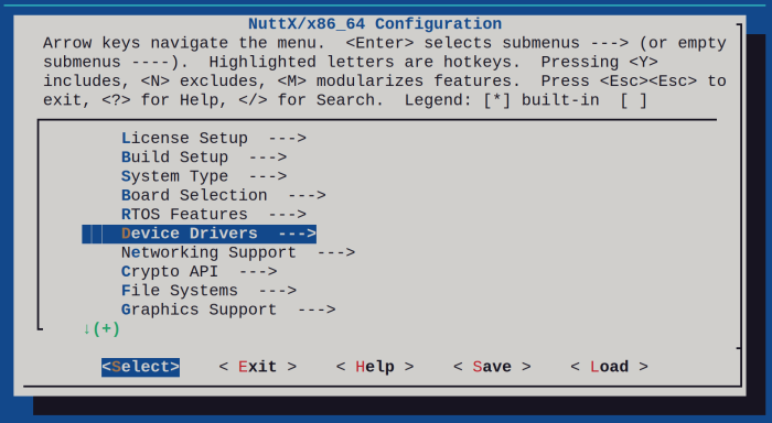
Enter inside Device Drivers:
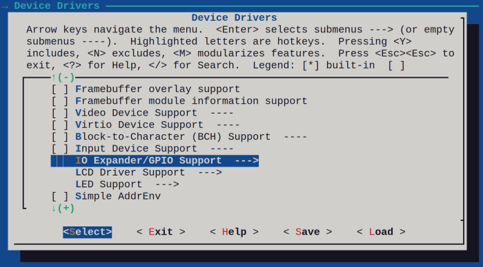
Then enter inside IO Expander/GPIO Support:
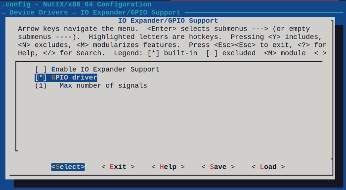
Enable the GPIO Driver:
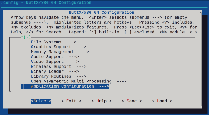
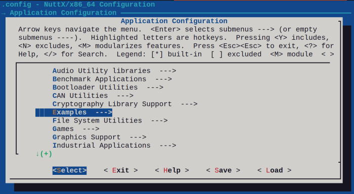
Return to main menu and enter inside Application Configuration:
Enter inside examples:
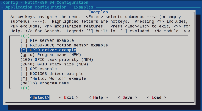
Enable the GPIO driver example:
You can leave the menuconfig and compile the source code (use -j8 to use more CPU cores) :
$ export PICO_SDK_PATH=~/pico-sdk
$ make -j8
CPP:  ~/nuttxspace/nuttx/boards/arm/rp2040/raspberrypi-pico/scripts/raspberrypi-pico-flash.ld-> ~/nuttxspace/nuttx/boards/arm/rp2040/raspberrypi-pico/LD: nuttx
Generating: nuttx.uf2
tools/rp2040/elf2uf2 nuttx nuttx.uf2;
Done.
Now press and hold BOOTSEL button in the board and connect the USB cable in the computer. You will see the disk unit RPI-RP2. Copy the file nuttx.uf2 to the RPI-RP2 unit.
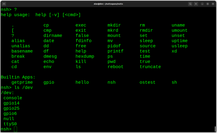
Connect a 3.3V USB/Serial to GP0 and GP1 pins as explained in the previous tutorial to get access to the NSH terminal and run "ls /dev" to confirm the gpio device files were created:
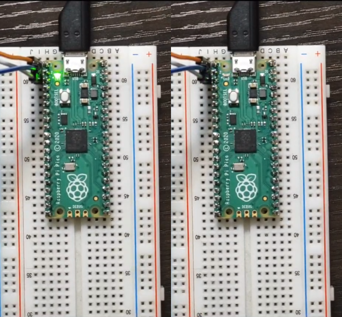
We can control the GPIO Output pin using passing -o value 1 or 0 to turn ON and turn OFF the LED:
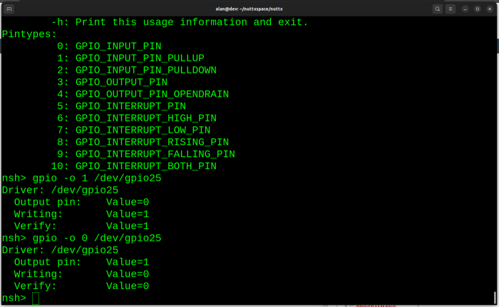
And you will see the LED blinking:
For GPIO inputs we have two options: with interrupt support and without interrupt support. The main difference is that for inputs without interrupt you need to do polling to detect changes of its state, but for GPIO with interrupt we can be "notified" about that changes.
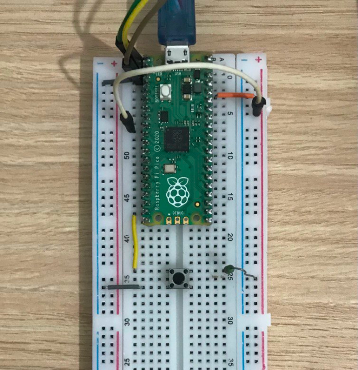
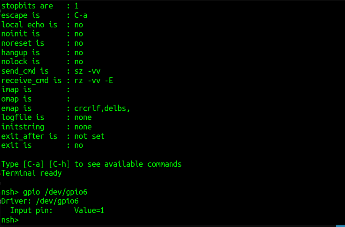
Let's start with a single example reading GPIO6 (that doesn't use interrupt in this case) you just need connect the pin 6 to positive (3.3V) this way:

The next step is to read GPIO11 (that has interrupt support enabled). But before to do our testing we need to see more some technical details looking at the source code.
If you open the rp2040_gpio.c file you will see it is looking for FALLING EDGE signal (see RP2040_GPIO_INTR_EDGE_LOW) in our GPIO 11 pin:
  ret = rp2040_gpio_irq_attach(irq,
                               RP2040_GPIO_INTR_EDGE_LOW,
                               rp2040gpio_interrupt,
                               &g_gpint[rp2040gpint->rp2040gpio.id]);
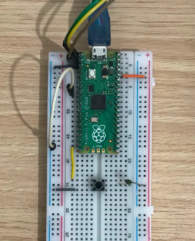
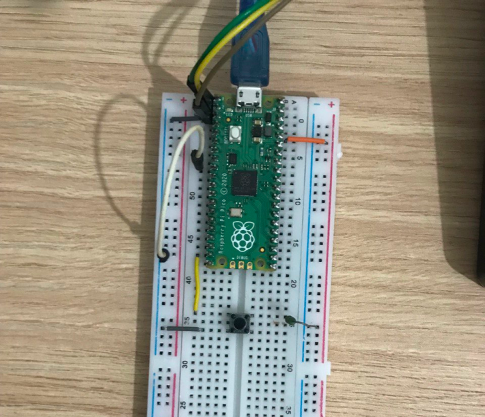
So, you need to include a pull-up resistor in the GPIO11 and connect the other side of the button to the GND, this way when you press the button the pin 11 goes down:
Now, finally we can test, and to do it we need to use the parameter "-w 1" that means we will wait for
the signal 1 (we enabled only 1 signal, look at GPIO driver at
menuconfig above). This way:
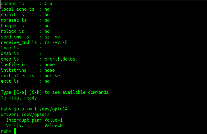
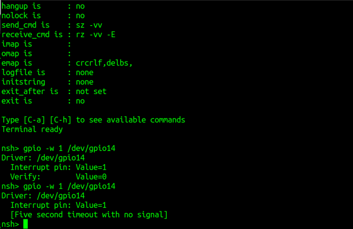
In this case the user pressed the button and the interrupt was generated. Case you didn't press the button in 5 seconds or there is some issue in your setup you will see the timeout message:
That all folks! I'm looking forward to our next tutorial.
Special thanks to Halysson Carvalho for supplying the images used here.


- Comments
- Write a Comment Select to add a comment

Hi tsj,
Thank you for your comment. I didn't know about Rasp PicoW using the WiFi chip to control the LED, initially I thought that information was incorrect because according with datasheet https://datasheets.raspberrypi.com/picow/pico-w-da... it uses an internal RP2040 GPIO pin (see page 4). Then I looked at schematic and in fact it is controlled by WL_GPIO0 pin. So, in this case we will need to implement the support in the Wireless driver to expose this pin as device file user LED. Please open an issue at https://github.com/apache/nuttx/issues and subscribe to NuttX mailing list https://nuttx.apache.org/community/ to discuss about it. In parallel you can try to use any other pin as user LED and connect a LED to that pin to test it (with a pull-down resistor). Cheers, Alan.
Actually it is already supported, see: https://nuttx.apache.org/docs/latest/platforms/arm...
To post reply to a comment, click on the 'reply' button attached to each comment. To post a new comment (not a reply to a comment) check out the 'Write a Comment' tab at the top of the comments.
Please login (on the right) if you already have an account on this platform.
Otherwise, please use this form to register (free) an join one of the largest online community for Electrical/Embedded/DSP/FPGA/ML engineers:


