


Using (Apache) NuttX USERLED Subsystem
In the previous article (https://embeddedrelated.com/showarticle/1623.php) we saw how to use GPIOs on NuttX testing on RaspberryPi Pico as example. In that article we used the GPIO output to control an LED, but there is a better way to do that. Of course, NuttX has an LED subsystem similar to Linux LED subsystem: it is called USERLED. Today we will see how to control LEDs using NuttX's USERLED subsystem.
![]()
Quick Links
- Part 1: Getting Started with (Apache) NuttX RTOS - Part 1
- Part 2: Getting Started with (Apache) NuttX RTOS Part 2 - Looking Inside and Creating Your Customized Image
- Part 3: Getting Started with NuttX RTOS on Three Low Cost Boards
- Part 4: Using GPIO in (Apache) NuttX RTOS
- Part 5: Using (Apache) NuttX USERLED Subsystem
- Part 6: Using (Apache) NuttX Buttons Subsystem
- Part 7: How to use I2C devices in (Apache) NuttX: Scanning for Devices
- Part 8: How to use I2C devices in (Apache) NuttX: Adding support for an I2C device in your board
- Part 9: How to use SPI devices in NuttX RTOS
The main advantage of using the USERLED subsystem instead of controlling the LEDs over GPIO is because USERLED can export all the LEDs as single device file (i.e.: /dev/userleds), this way with a single write operation you can turn ON or OFF any LED of your board.
You can also use a command-line tool like the “printf” command to control the NSH LEDs. Yes, there is a “printf” command on your Linux machine and NuttX has it too. If you've never used it on your Linux, don't worry, even the most experienced Linux user doesn't know all the hidden commands (you can type: $ man 1 printf to read the command manual).
Another advantage of using USERLED is that if you developed your initial NuttX application to work on board "A" and later switched to board "B" which has the same number of LEDs, you do not need to modify your application. All you need to do is map the LEDs on your B board using the USERLED subsystem.
The raspberrypi-pico board already has the LED mapped correctly to green LED soldered on the board. So you can look how it is implemented:
In the file boards/arm/rp2040/raspberrypi-pico/include/board.h you have the BOARD_NLEDS definition, it defines how many LEDs controlled by RP2040 you have in your board.
In the file boards/arm/rp2040/raspberrypi-pico/src/rp2040_pico.h you have GPIO_LED1 definition, it defines which GPIO pin is used to control that LED.
And finally in the file boards/arm/rp2040/raspberrypi-pico/src/rp2040_userleds.c you have the functions to initialize and control the LED(s) of your board. These functions are used by drivers/leds/userled_lower.c to create an abstraction layer common for all boards and finally drivers/leds/userled_upper.c uses the lower half functions (from userled_lower.c) and register the device file at /dev (normally as /dev/userleds).
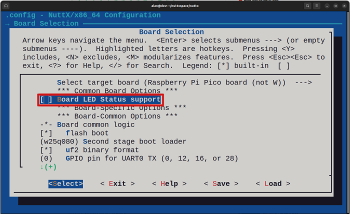
Before using the USERLED subsystem you need to disable the "Board LED Status support" (CONFIG_ARCH_LEDS). It is necessary because by default NuttX uses the LEDs on the board to indicates its initialization status, so it is used for diagnose purpose.
If your board's LED is lit it means that your board has been initialized correctly, if it is blinking (at a frequency of 2 Hz) it means that NuttX faced some issue while executing the initialization process.
So the first thing we need to do is disable this feature to allow the LED to be used for another purpose. In this case you need to run:
$ make menuconfig
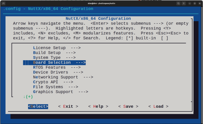
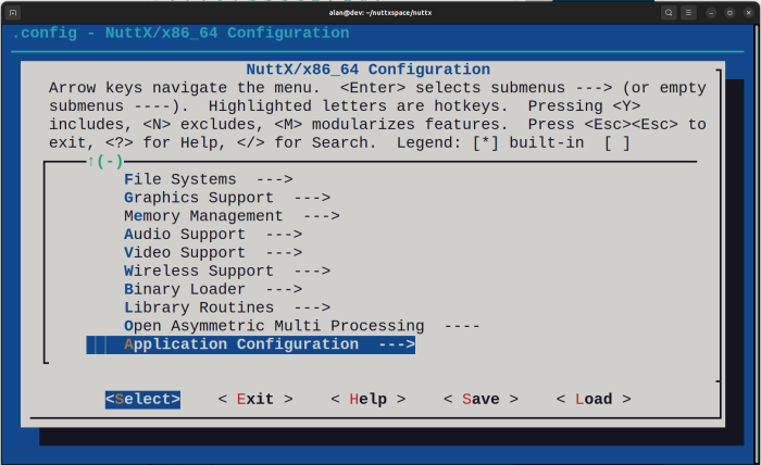
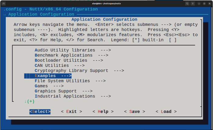
Enter inside Board Selection:
Then disable the "Board LED Status support" pressing SPACE
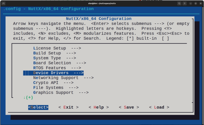
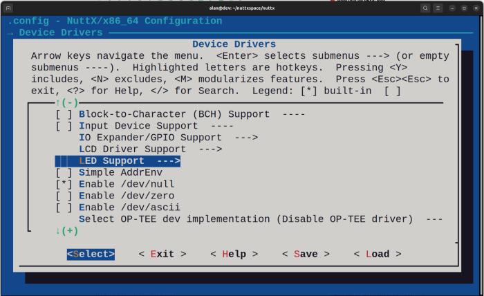
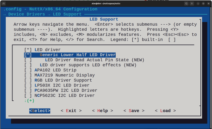
Now you can enter inside Device Driver:
Now you can exit from menuconfig and compile your source code as you did in the previous tutorial:
$ make -j
Create version.h
LN: platform/board to /home/alan/nuttxspace/apps/platform/dummy
Register: leds
Register: hello
Register: ostest
Register: nsh
Register: getprime
Register: sh
CPP: nuttx/boards/arm/rp2040/raspberrypi-pico/scripts/raspberrypi-pico-flash.ld-> nuttx/boards/arm/rp2040/raspberry
LD: nuttx
Generating: nuttx.uf2
tools/rp2040/elf2uf2 nuttx nuttx.uf2;
Done.
Finally you can flash the nuttx.uf2 file on your board, to do it press and hold the BOOTSEL button on your board and connect the USB cable to your computer. You will see the RPI-RP2 disk in your file manager and then just copy the file to it.
Connect the USB/Serial adapter in the pins GP0, GP1 and GND as explained on previous tutorials and use some serial communication program like minicom, picocom, etc to access the NuttShell (NSH).
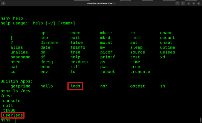
Type "help" or question mark ("?") to see the available commands, you will see there is a build-in application called "leds" and if you type: "ls /dev" you will see there is a userleds device file:
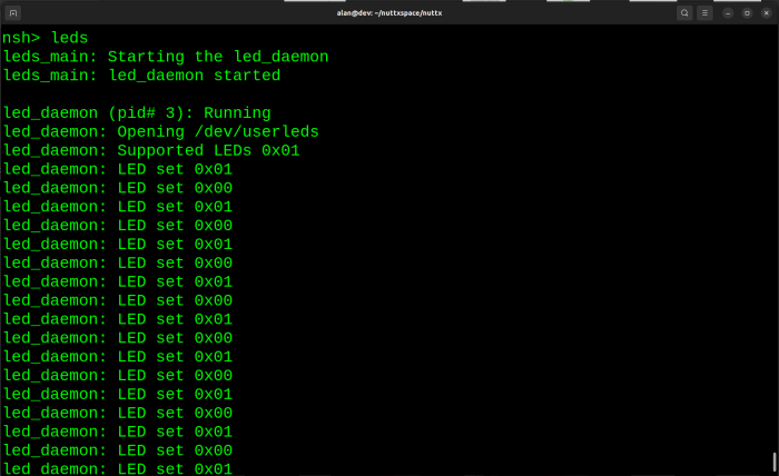
You can run the "leds" program to see the LED blinking each 1 second:
As I said before, you can use the command "printf" to control the LEDs of your board from command line.
To turn ON your board LED run:
nsh> printf \x00000001 > /dev/userledsAnd to turn OFF your board LED run:
nsh> printf \x00000000 > /dev/userleds
These values are the hexadecimal 32-bit presentation of the values 1 and 0. It means that you can control up to 32 LEDs at same time writing a 32-bit value to /dev/userles!
That is it! Very easy to use the NuttX USERLED subsystem!
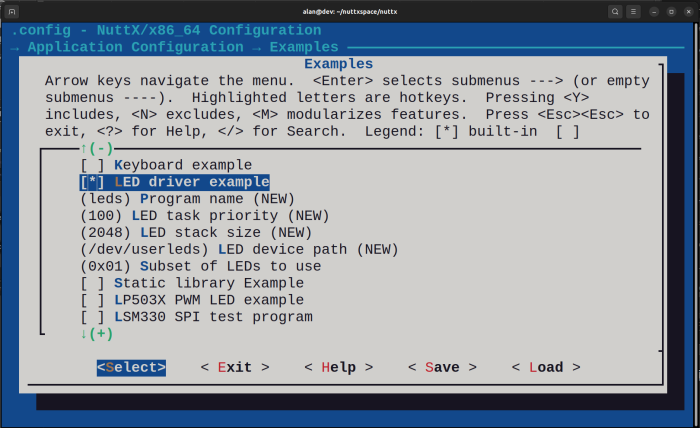
Now I have a challenge for you: put your board in a breadboard and add 8 LEDs with current limiting resistors such as 470R or 1K and connect them to your board GPIO pins. Then define the pins number for each LED in the rp2040_pico.h and include them in the g_ledcfg[BOARD_NLEDS] array. Important: don't forget to change BOARD_NLEDS to 8 in the file boards/arm/rp2040/raspberrypi-pico/include/board.h and also don't forget the change the "Subset of LED to use" in LED example application to 0xff. If you succeed, please let me know!


- Comments
- Write a Comment Select to add a comment
To post reply to a comment, click on the 'reply' button attached to each comment. To post a new comment (not a reply to a comment) check out the 'Write a Comment' tab at the top of the comments.
Please login (on the right) if you already have an account on this platform.
Otherwise, please use this form to register (free) an join one of the largest online community for Electrical/Embedded/DSP/FPGA/ML engineers:


